WP4 — Control of Grid-Forming Converters (Final Report)#
Authors
S. Kenzelmann — December 12, 2025
1. Introduction#
The transition toward decentralized energy systems has placed microgrids at the forefront of modern power networks. These systems promise flexibility, resilience, and sustainability, but their successful operation depends on one critical element: robust converter control strategies. In particular, grid-forming converters play a central role in maintaining stability and ensuring seamless interaction between distributed energy resources, whether operating in islanded mode or connected to the main grid.
This work package addresses these challenges by developing advanced control strategies for grid-forming converters within a microgrid environment that includes multiple converters. Beyond traditional stability concerns, the growing threat of cyberattacks adds a new dimension to system design, requiring not only electrical robustness but also digital resilience. To achieve this, the interface between converter control and the Energy Management System (EMS) has been specified and implemented, enabling coordinated operation and optimal resource utilization.
Before deployment on the HEI converter platform, all proposed solutions have undergone rigorous simulation and testing to validate performance under diverse operating conditions. The work package comprises three main sections:
- Electrical stability and control fundamentals — establishes the foundation for converter control, focusing on dynamic stability and power-sharing mechanisms essential for reliable microgrid operation.
- Integration and optimal operation — places converters in the broader context of microgrid management, ensuring alignment with the objectives defined in WP3 and enabling efficient coordination between distributed resources.
- Cybersecurity and resilience — examines vulnerabilities at both converter and microgrid levels, assessing the impact of cyber threats and developing mitigation strategies to safeguard system integrity.
By combining advanced control techniques with cybersecurity measures, this work package aims to deliver a resilient, future-ready microgrid architecture.
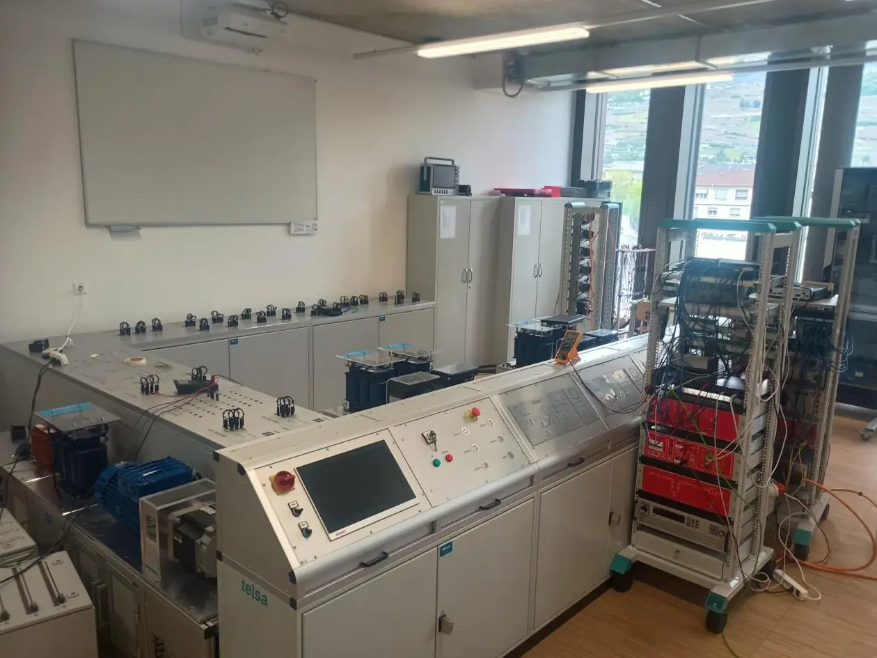 Figure 1: Two POETIC converters within the GridLab dispatch.
1.1 GridLab dispatch#
The GridLab dispatch emulates a multi-level power system comprising high-voltage (HV), medium-voltage (MV), and low-voltage (LV) domains. All domains are simulated and electrically scaled to a nominal 400 V level to enable practical laboratory testing, uniform instrumentation, and safe operation. This scaling preserves the essential dynamics of inter-level interactions (e.g. upstream grid impedance, feeder characteristics, and load profiles) while allowing the use of standard laboratory hardware and measurement equipment.
A distribution-level segment hosts two POETIC power converters that form the core of the experiments and validations reported in this work package. This segment is designed to operate in both grid-connected and islanded modes with seamless transition capability. It may be logically islanded (decoupled from the upstream emulated grid) or re-synchronized and re-coupled depending on operational objectives, contingency events, or testing procedures.
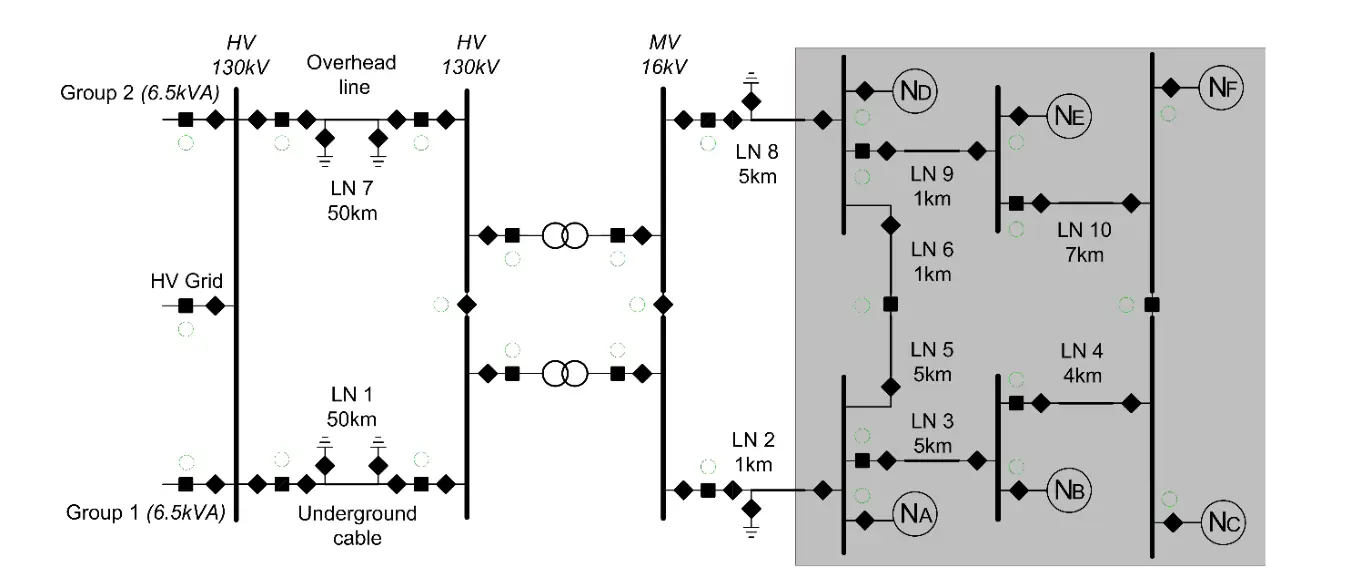 Figure 2: GridLab dispatch.
Different operation modes can be distinguished:
Grid-Connected Mode (segment coupled)
- The segment is electrically connected to the emulated upstream grid.
- Converters operate in grid-forming mode but may align their voltage/frequency reference with the upstream grid (via synchro-check or phase-synchronization logic).
- Objectives: support local voltage profile, regulate power flows, provide ancillary behaviours (e.g. fault ride-through per profile), and prepare for potential islanding.
Islanding Mode (segment decoupled)
- The segment is electrically isolated from the upstream grid.
- Converters must autonomously establish and maintain voltage and frequency, ensure stable power-sharing, and handle load variations and faults locally. In our setup there is no automatic islanding detection (based on voltage magnitude, frequency deviation, RoCoF, vector shift, or PCC breaker status) — islanding is performed voluntarily.
- A black-start procedure is used to start up the islanded microgrid with only converter-based resources.
- Objectives: maintain service continuity, provide black-start capability, and support controlled reconnection when appropriate.
Transition Mode (coupling/decoupling)
- Controlled opening/closing of the point of common coupling (PCC) based on pre-defined criteria (voltage, frequency, phase angle, RoCoF, THD).
- Smooth transitions require robust synchronization, ramping, and droop coordination.
1.2 POETIC prototyping platform#
The POETIC platform is a highly configurable power converter designed for advanced research and testing. It integrates a dedicated CPU for real-time control and leverages Typhoon HIL for Hardware-in-the-Loop simulation and Rapid Control Prototyping (RCP). POETIC supports multiple power-stage configurations; for this project, a two-level SiC-based topology was used to achieve high efficiency and fast switching performance. The system includes versatile filtering options and circuit breakers, enabling controlled connection and disconnection from the grid under various operating scenarios. Control algorithms are deployed and validated directly on the Typhoon HIL environment, ensuring accurate real-time emulation before physical implementation.
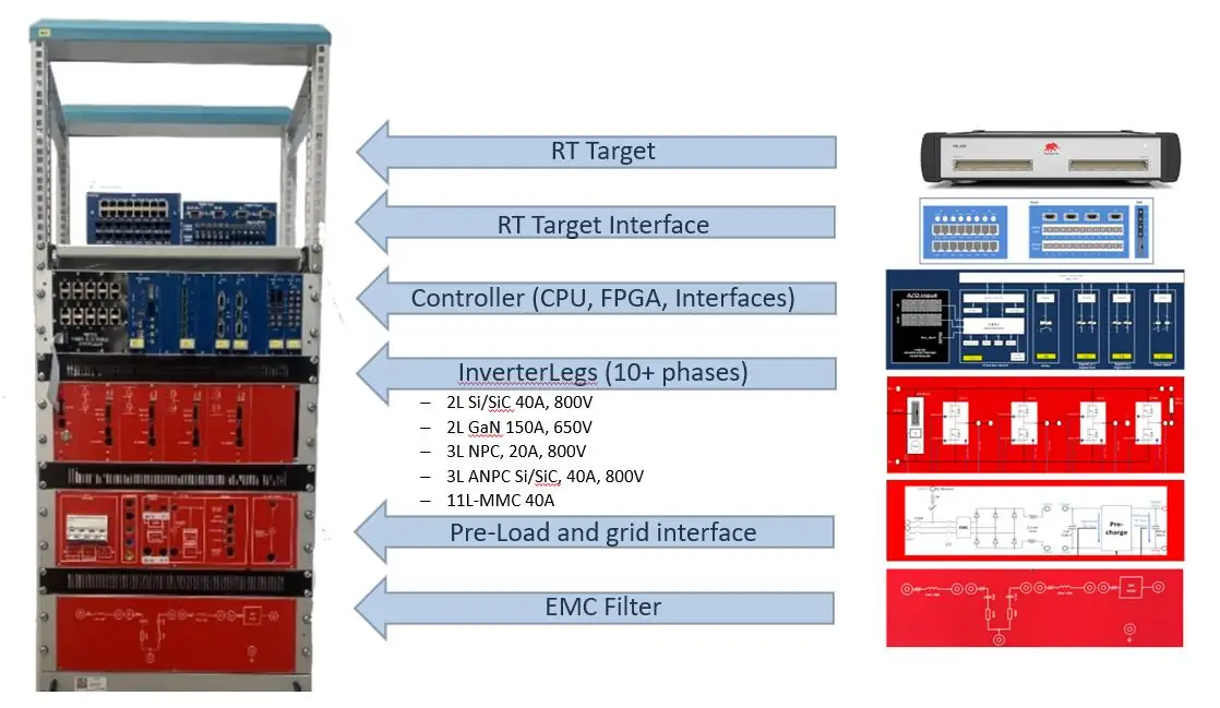 Figure 3: POETIC converter platform.
The system simulates a PV-inverter or battery-inverter system with the following components:
- DC power supply or battery
- Pre-charge module
- Boost stage (optional, replacing the power supply with a battery)
- Inverter
- LCL filter
- Contactors for DC and AC voltages
- Three-phase measurement of inverter currents and voltages
- Three-phase measurement of grid currents and voltages
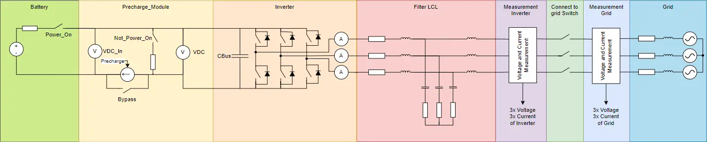 Figure 4: Complete DER system.
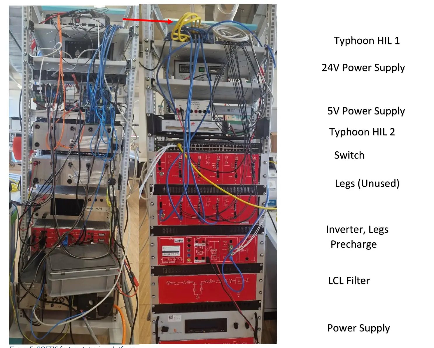 Figure 5: POETIC fast prototyping platform.
2. Control design#
The control of power converters is a cornerstone of modern microgrid operation. In systems where multiple converters interact under varying conditions — such as grid-connected and islanded modes — robust and adaptive control strategies are essential to ensure stability, reliability, and resilience. This chapter introduces the principles, objectives, and design considerations for grid-forming converter control, which enables converters to establish and maintain voltage and frequency references even in the absence of a strong upstream grid.
Microgrids present unique challenges compared to traditional power systems: their reduced inertia, high penetration of power electronics, and dynamic operating modes demand advanced control architectures that can handle fast transients, maintain power quality, and support seamless transitions between operating states.
The primary objectives of converter control in this context are:
- Voltage and frequency regulation — maintain stable voltage and frequency under varying load and generation conditions.
- Power sharing — ensure proportional and stable sharing of active and reactive power among multiple converters without high-bandwidth communication.
- Mode transition — enable smooth switching between grid-connected and islanded operation without service interruption.
- Fault ride-through — provide resilience during short-duration faults and disturbances.
- Cybersecurity awareness — incorporate control strategies that remain robust against malicious data manipulation or communication failures.
Converter control is typically organized into hierarchical layers:
- Inner control loops — fast current and voltage regulation to ensure converter stability and protect hardware.
- Outer control loops — implement grid-forming functionalities such as droop control or Virtual Synchronous Machine (VSM) behaviour.
- Supervisory control — coordinates setpoints and optimizes operation based on system-level objectives.
- Energy Management System — exchanges operational data and constraints with the EMS for optimal dispatch.
Droop control has been chosen as the primary strategy for grid-forming converters because it ensures minimal dependency on high-bandwidth communication with the EMS. This decentralized approach allows converters to share power and maintain voltage and frequency stability using only local measurements, reducing complexity and improving robustness. Importantly, droop control can continue operating effectively even if communication with the EMS is lost (such as during a cyberattack), thereby preserving microgrid stability and service continuity.
In the absence of the physical inertia of rotating machinery, sudden load changes might lead to fast frequency changes — even oscillations — which jeopardize grid stability. Therefore, implementing some form of inertia in a microgrid with mostly renewable sources is a must.
Grid-forming control synthesizes a stiff voltage source with embedded virtual inertia and damping to stabilize the microgrid under load changes and faults. Typical implementations include:
Droop control (P–f and Q–V):
where \(f_0\), \(V_0\) are the nominal frequency and voltage, \(P^\star\), \(Q^\star\) are the setpoints, and \(K_P\), \(K_Q\) are droop coefficients. Proper selection of \(K_P\), \(K_Q\) ensures stable power-sharing among converters without communication (primary control).
Virtual Synchronous Machine (VSM) — emulates swing-equation dynamics:
where \(H\) is the virtual inertia, \(D\) the damping, \(P_m\) the mechanical-equivalent input (from setpoints/EMS), and \(P_e\) the electrical power. VSM improves frequency quality (lower RoCoF), oscillation damping, and resilience.
PLL-less operation — in islanding, grid-formers must not depend on a phase-locked loop for the fundamental reference; instead, they create the reference. In grid-connected mode, synchronization to the upstream grid is achieved via controlled phase-alignment mechanisms (e.g. frequency/phase offset loops, synchro-check relays) while preserving internal grid-forming dynamics.
2.1 Grid-forming converter control#
There are five main blocks: the power calculations, the droop regulation/calculation, the voltage and current regulation, the division by the DC-bus voltage that yields a modulation value for every phase, and finally the PWM modulation.
2.2 Droop control#
Droop control is implemented as the primary strategy because it enables converters to operate in both grid-following and grid-forming modes without requiring continuous communication with the EMS. This decentralized approach ensures robust operation even under communication loss or cyberattack scenarios.
In grid-connected mode, the inverter delivers the power setpoint defined by the user. For example, if the load requires 10 kW and the inverter is set to 20 kW, an excess of 10 kW is injected into the grid. Conversely, if the load exceeds the inverter’s capacity, the grid supplies the remaining power.
In islanded mode, the inverter supplies only the power required by local loads, maintaining voltage and frequency autonomously.
Note
Currently, the system does not support black-start capability — the inverter must be running before the grid can be disconnected. Future developments will address this limitation.
A key advantage of droop control is its ability to synchronize multiple inverters without communication. Each inverter adjusts its output based on local measurements, balancing active and reactive power through predefined droop characteristics. This self-organizing behaviour ensures stable operation and proportional power-sharing.
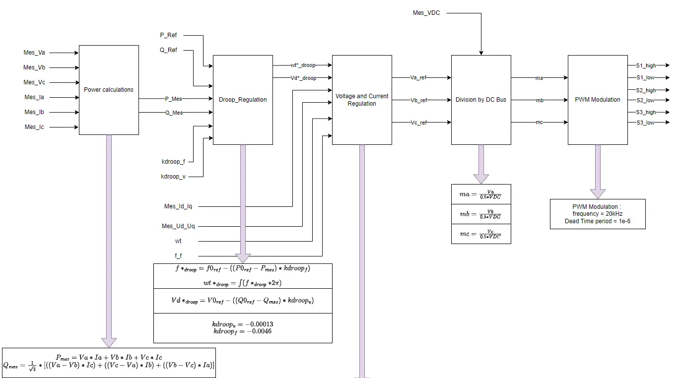 Figure 6: Droop control.
The droop equations are:
The frequency reference is derived from the difference between the active power setpoint \(P_0^{\text{ref}}\) and the measured power \(P_{\text{mes}}\), multiplied by the droop coefficient \(k_{\text{droop},f}\). This deviation is subtracted from the nominal frequency \(f_0\) (typically 50 Hz) to obtain \(f^*_{\text{droop}}\). To generate the phase-angle reference, this frequency is converted to angular speed (×\(2\pi\)) and integrated, with a rollover at \(2\pi\) (resetting to zero), yielding a periodic signal in \([0, 2\pi]\) that serves as the angle reference.
Similarly, the voltage reference \(V_{d,\text{droop}}^{*}\) is computed from the reactive-power error multiplied by \(k_{\text{droop},v}\) and subtracted from the nominal voltage \(V_0\).
Example behaviour
- If \(P_{\text{mes}} = P_0^{\text{ref}}\), the frequency stays at 50 Hz.
- If \(P_{\text{mes}} > P_0^{\text{ref}}\), the frequency decreases below 50 Hz.
- If \(P_{\text{mes}} < P_0^{\text{ref}}\), the frequency increases above 50 Hz.
This mechanism ensures autonomous adjustment of frequency and voltage based on power imbalances, enabling stable operation without explicit load information or centralized communication.
2.3 Virtual inertia#
Modern microgrids often operate with little or no physical inertia because most distributed energy resources are interfaced through power electronics rather than synchronous machines. This lack of inertia makes the system highly sensitive to disturbances such as sudden load changes or generation fluctuations, leading to rapid frequency deviations and potential instability.
In a physical setup with a synchronous generator, inertia comes from the rotating mass of the generator’s rotor. This mass resists changes in rotational speed, which directly stabilizes system frequency during disturbances. When a sudden load change occurs, the rotor’s stored kinetic energy temporarily absorbs or supplies power, slowing the rate of change of frequency (RoCoF).
The governor monitors generator speed and adjusts mechanical input power (usually by controlling steam, water, or fuel flow to the turbine):
- If frequency drops (load increases), the governor opens the valve to increase mechanical power (secondary control).
- If frequency rises (load decreases), it reduces input power.
The dynamic behaviour is described by the swing equation:
where \(H\) is the inertia constant, \(P_m\) is mechanical power, and \(P_e\) is electrical power.
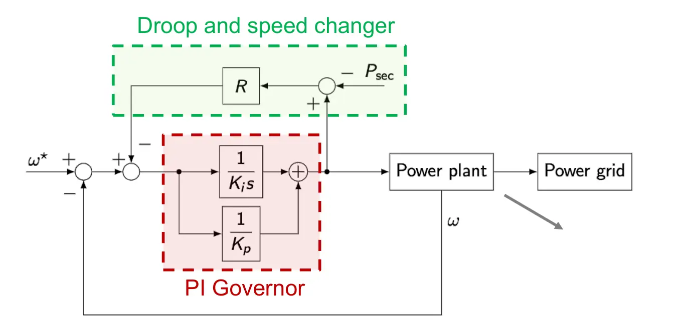 Figure 7: Plant model for a rotating hydropower system.
Virtual inertia provides a synthetic inertial effect by temporarily storing and releasing energy through the converter’s DC link or associated energy storage. When a disturbance occurs, the converter adjusts its power output proportionally to the RoCoF, slowing down frequency deviations and giving secondary controls time to react. The most common approach is the Virtual Synchronous Machine (VSM):
where:
- \(H\) — virtual inertia constant
- \(D\) — damping factor
- \(P_m\) — mechanical-equivalent input (setpoint or EMS command)
- \(P_e\) — electrical power output
- \(\omega\) — angular speed
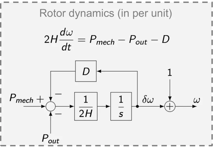 Figure 8: Implementation of inertia in the converter control.
2.4 Phase angle determination#
A Phase-Locked Loop (PLL) is a control mechanism used to estimate the phase angle and frequency of an AC signal, typically for synchronization. In grid-following converters, a PLL is essential because the converter must align its internal reference frame with the external grid voltage to inject power accurately. In grid-forming control, however, a PLL is generally not used: the converter itself establishes the voltage and frequency reference for the microgrid.
2.4.1 With PLL#
Although a PLL is not used during normal grid-forming operation, it becomes necessary during initial synchronization with the main grid or when reconnecting after islanded operation. The converter must align its internal reference angle with the grid voltage before closing the breaker; a PLL estimates the grid angle \(\theta\) from three-phase measurements. Once locked, the converter can transition smoothly from islanded to grid-connected mode.
2.4.2 Without PLL#
In droop-controlled grid-forming converters the frequency is not measured from an external source but is part of the control loop. Active power \(P\) and frequency \(f\) are related by
where \(f_0\) is the nominal frequency (e.g. 50 Hz), \(P_0\) the reference active power, and \(k_P\) the droop coefficient (Hz/W). As output power changes, the converter slightly adjusts its frequency to share load proportionally with other converters, enabling decentralized control without a PLL.
2.5 Voltage and current control#
The voltage and current regulations are performed in the dq-axis frame. First, the voltage is regulated on the d-axis with the \(V_{d,\text{droop}}^{*}\) reference coming from the droop control. The q-axis voltage reference is always 0. The PI regulator for the voltage transforms the voltage error into a current reference for the d and q axes; the angle for the dq-axis rotation is given by the droop control.
The final voltage reference is divided by the DC-link voltage to obtain the modulation indices for the three phases. The PWM modulation then takes the modulation values for every phase and pulses at 20 kHz for 6 outputs (2 per phase) with a 1 µs dead-time between switching for safety.
2.6 State machine#
Two state machines are implemented: a main state machine and a protection state machine for handling system errors.
2.6.1 Protection#
The first state machine handles alarms. If certain measured quantities
exceed configured limits, the alarm state machine raises an alarm and stops
the system immediately; the error must be cleared to start the system again.
For example, if the DC-bus voltage exceeds its limit, Error_Bus is raised
and the main Error flag is also set.
2.6.2 Main state machine#
The second state machine drives the steps the system takes to operate correctly, including startup (charging the DC bus, ramping up the inverter voltage, etc.).
2.7 Black start#
A black start is the controlled energization of an islanded microgrid from a complete shutdown without external grid support. The process ensures a stable voltage and frequency reference for subsequent synchronization of converters and connection of loads. The black-start procedure is split into four steps:
Step 1 — Initial energization. Select one grid-forming converter as the reference. Energize its DC source (e.g. battery or fuel cell) and activate inner and outer control loops. Configure the converter in grid-forming mode with nominal frequency (50 Hz) and a limited AC voltage of 50 V RMS to minimize inrush currents and allow safe synchronization. Maintain frequency deviation within ±0.1 Hz during this stage.
Step 2 — Synchronization of additional converters. Bring the second converter online and synchronize it with the first (identical procedure to synchronizing with the main grid). Once aligned, switch the second converter to grid-forming mode and close its breaker. Repeat for all remaining converters until the microgrid has multiple grid-forming units operating in parallel.
Step 3 — Voltage ramp-up. After all converters are synchronized and stable, gradually increase the voltage reference from 50 V RMS to nominal 230 V RMS at a typical ramp rate of 10–20 V/s to avoid magnetizing inrush and maintain stability.
Step 4 — Load and resource restoration. Begin connecting critical loads and additional DERs in sequence. Ensure each resource synchronizes to the established reference before closing its breaker. Apply soft-start or pre-charge circuits for transformers and large loads.
Warning
Due to lack of resources, the black-start functionality has not been implemented in the final prototype.
3. EMS interface#
3.1 Communication protocol#
The system uses a Modbus communication infrastructure. The Modbus server holds the commands; Modbus clients continuously read values from the server to know what to do. The Modbus server can be implemented either with the Typhoon controller or with an external Python interface. The Modbus clients are the systems hosting an inverter that connects to the grid.
3.3 EMS control layers#
- Primary (local) control — fast inner loops for current/voltage regulation; outer droop/VSM layers for frequency and voltage; harmonic compensation if needed. Implemented in the controller (Typhoon HIL).
- Secondary (supervisory) control — restores voltage/frequency to nominal after primary droop-induced deviations; coordinates setpoints between converters. Implemented at the Modbus-server level.
- Tertiary (EMS interface) — economic dispatch, energy scheduling, and constraint management (e.g. SOC limits, thermal limits, demand response). This layer communicates with the EMS using a specified interface, and is implemented at the Modbus-server level.
4. Threats and mitigation concepts#
Cybersecurity is a critical aspect of modern microgrid operation, as control systems increasingly rely on digital communication and remote interfaces. A successful attack could compromise stability, disrupt power delivery, or even damage hardware. The converter control architecture incorporates multiple layers of defence — combining inherent design choices with active protection mechanisms — at the local converter level.
4.1 Inherent resilience through droop control#
The foundation of the control strategy is droop control, which enables decentralized operation without continuous reliance on the EMS. By using only local measurements for voltage and frequency regulation, droop control ensures stable converter operation even if EMS communication is lost or corrupted during a cyberattack. This independence significantly reduces the attack surface and guarantees service continuity under adverse conditions.
4.2 Data integrity and validation#
All data exchanged between the converter and the EMS undergoes strict integrity checks. These checks validate the authenticity and consistency of incoming commands and reference values, rejecting any data that appears corrupted, incomplete, or outside predefined operational limits. This prevents malicious actors from injecting harmful setpoints or destabilizing instructions into the control loop. Additionally, all reference values communicated from the EMS are subject to rate limiting to avoid the effects of flickering values.
4.3 Controlled communication protocols#
Communication with the EMS is deliberately minimal in terms of exchanged information and uses Modbus-based protocols with continuous data refresh, in order to cope with forged packets. This approach reduces exposure to common network vulnerabilities while ensuring that essential operational data — such as power limits, state of charge, and scheduling constraints — is transmitted securely and efficiently.
Note
An additional secure layer such as TLS could make the communication much more secure; however, the controller used (Typhoon HIL) does not support this feature inherently.
4.4 Hardware protection layer#
The converter platform incorporates a multi-layered protection and stability framework to ensure safe and reliable operation under both normal and fault conditions. At the core is a dedicated hardware protection layer — the final safeguard against physical damage. This layer enforces strict limits on current, voltage, and temperature; operates independently of external commands; and remains completely isolated from remote access — guaranteeing equipment integrity even during severe cyber intrusions and preventing cascading failures.
4.5 Summary of defense strategy#
The combined measures — decentralized droop control, data-integrity checks, minimal and secure communication, and hardware-level protection — create a robust cybersecurity framework. This multi-layered approach not only mitigates the risk of cyberattacks but also ensures that the microgrid can continue operating safely and reliably under compromised conditions.
5. Testing#
In this chapter the basic functionalities of the converter are tested. The stability of the microgrid can be classified as in the figure below; we test both grid-connected and islanded stability, in particular in view of the transient stability.
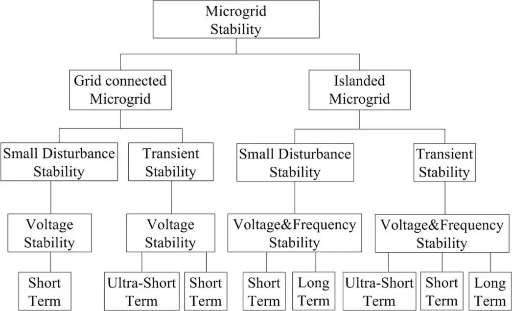 Figure 16: Stability criteria. Adapted from Z. Shuai et al., “Microgrid
stability: Classification and a review”, Renewable and Sustainable Energy
Reviews 58 (2016) 167–179, doi:10.1016/j.rser.2015.12.201.
Figure 16: Stability criteria. Adapted from Z. Shuai et al., “Microgrid
stability: Classification and a review”, Renewable and Sustainable Energy
Reviews 58 (2016) 167–179, doi:10.1016/j.rser.2015.12.201.
The tests presented here are simulations only on the realtime target; experimentation on the real setup is reported in the WP5 report.
The simulations are carried out on Typhoon HIL using two grid-forming inverters in continuous mode. The simulated three-phase grid is shown below.
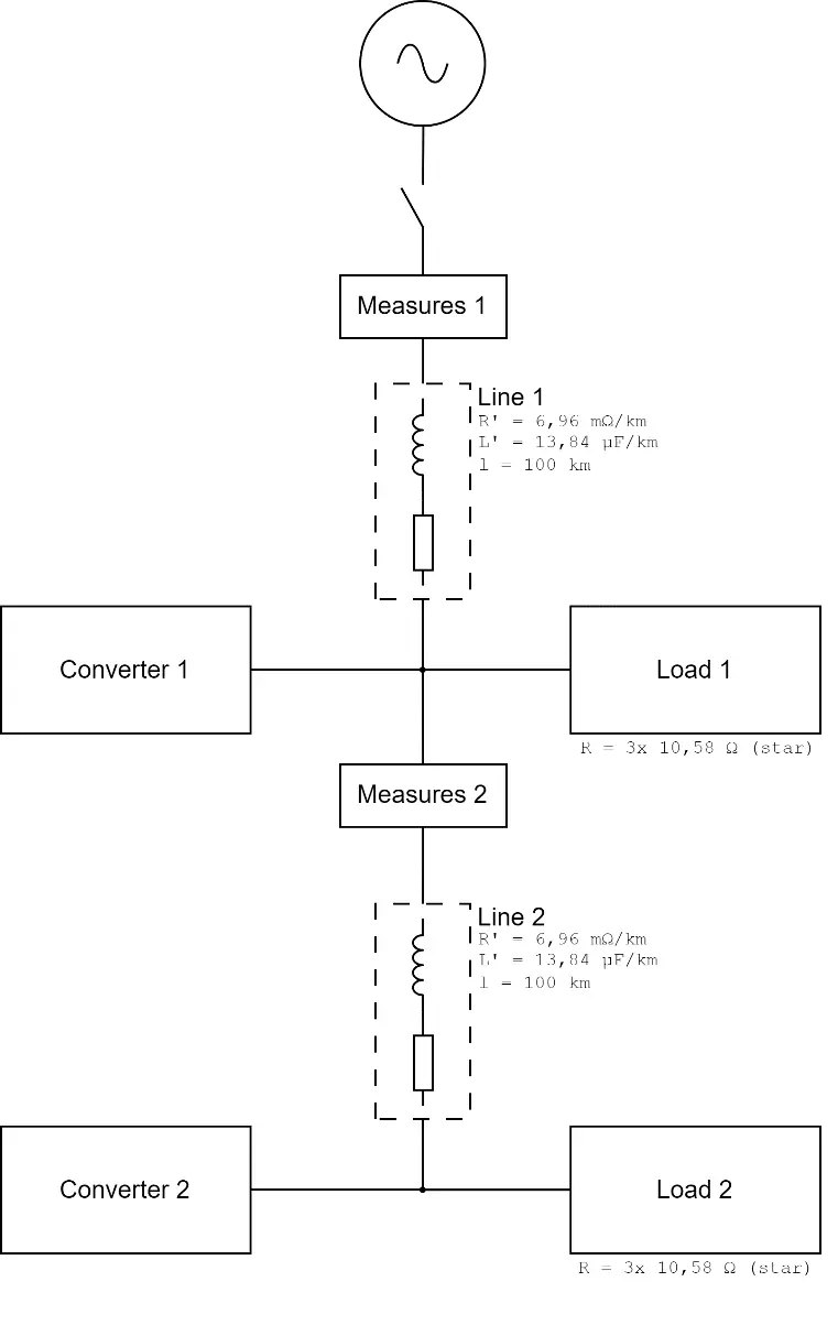 Figure 17: Schematic of the simulated grid.
5.1 Load step of 15 kW (single inverter)#
A 15 kW load step is applied to resistive load 1. The voltage and current responses are recorded for two inertia values.
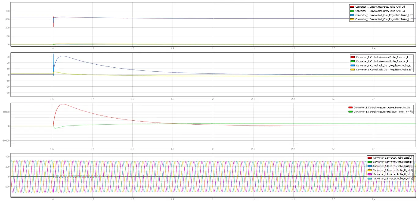 Figure 18: Voltage and current during a 15 kW load step. Inertia \(H=0.001\).
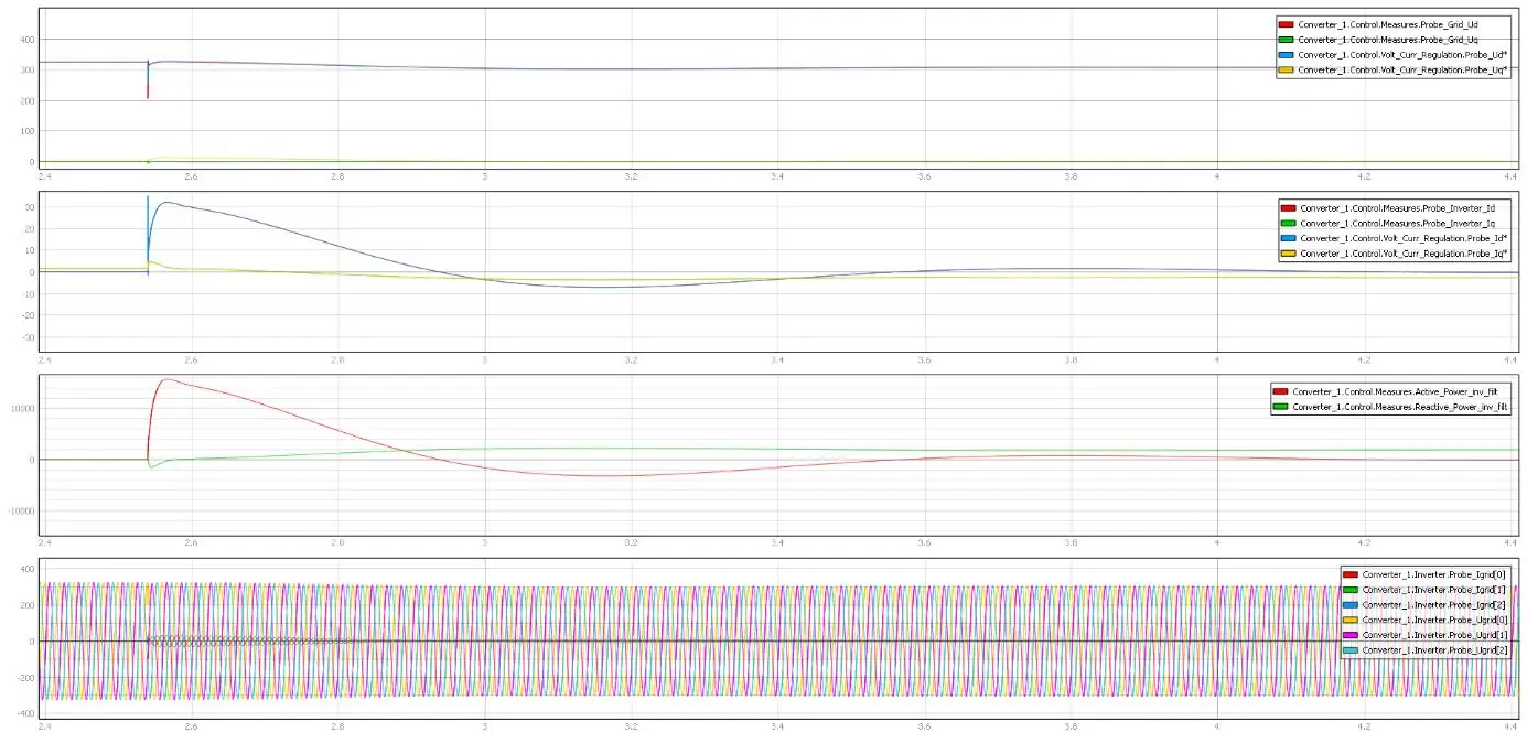 Figure 19: Voltage and current during a 15 kW load step. Inertia \(H=0.1\).
Switching on the load causes a voltage drop on the line between load and grid. As the load is directly connected to the inverter output, the inverter cannot react instantaneously to the voltage drop and a current peak is measured at the inverter output. The reference voltage given to the reactive-power droop is 325 V (peak phase voltage); when the load is activated, the voltage at the inverter is below 325 V, so the inverter injects reactive power into the grid.
5.2 Load step of 15 kW with two inverters#
Both converters are connected to the grid with a load setpoint of 0 kW and inertia of 0.001. A 15 kW load step is performed at load 1.
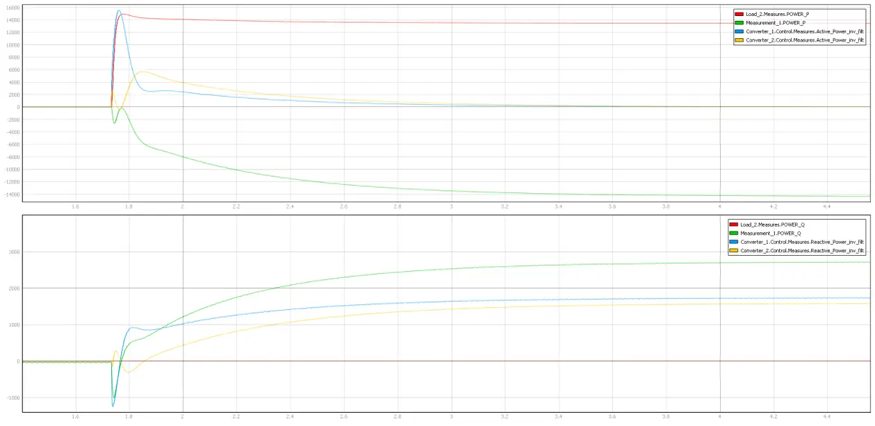 Figure 20: Active and reactive power of grid and converters 1 and 2 during a
15 kW load step. \(H_1 = H_2 = 0.001\).
Figure 20: Active and reactive power of grid and converters 1 and 2 during a
15 kW load step. \(H_1 = H_2 = 0.001\).
The measurements are repeated with \(H_1 = 1\) for converter 1:
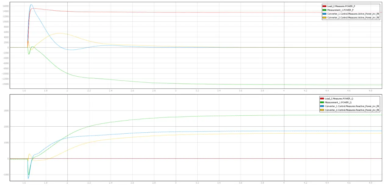 Figure 21: As Figure 20 but with \(H_1 = 1\) and \(H_2 = 0.001\).
The two converters share the reactive power injected into the network because of the voltage drop on the line.
5.3 Fault ride-through#
A grid voltage sag is simulated to assess the stability of the converters connected to the grid.
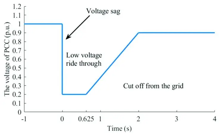 Figure 22: Curve of the voltage sag on the grid. Source: “Fault
Characteristic and Low Voltage Ride-Through Requirements Applicability
Analysis for a Permanent Magnet Synchronous Generator-Based Wind Farm”,
doi:10.3390/en12173400.
Figure 22: Curve of the voltage sag on the grid. Source: “Fault
Characteristic and Low Voltage Ride-Through Requirements Applicability
Analysis for a Permanent Magnet Synchronous Generator-Based Wind Farm”,
doi:10.3390/en12173400.
The next figure shows the simulation result during a voltage sag when resistive load 1 and converter 1 are connected to the grid; the inverter injects 5 kW.
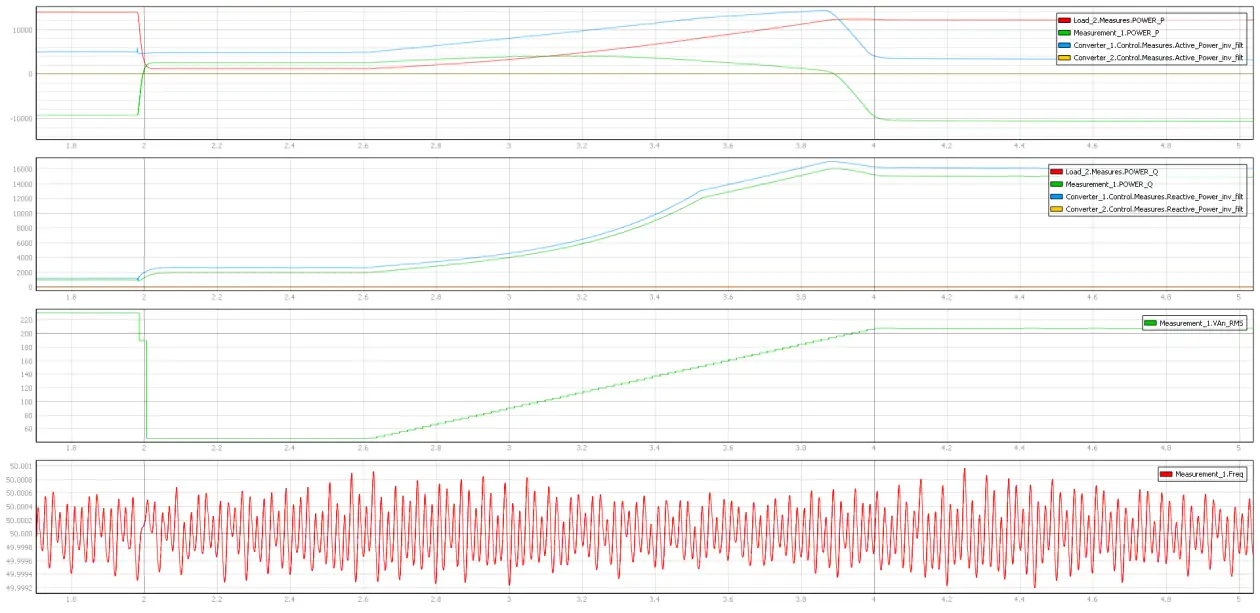 Figure 23: Power supplied by the inverter during the voltage sag.
The current is limited to 35 A by the regulation. For a grid voltage of 80 V the inverter cannot inject its maximum power of 15 kW.
5.4 Grid disconnect#
Both inverters are connected to the grid together with load 1; inverters 1 and 2 are set to feed 2.5 kW and 5 kW respectively. The grid is then disconnected and the two inverters operate in isolated mode with the 15 kW load.
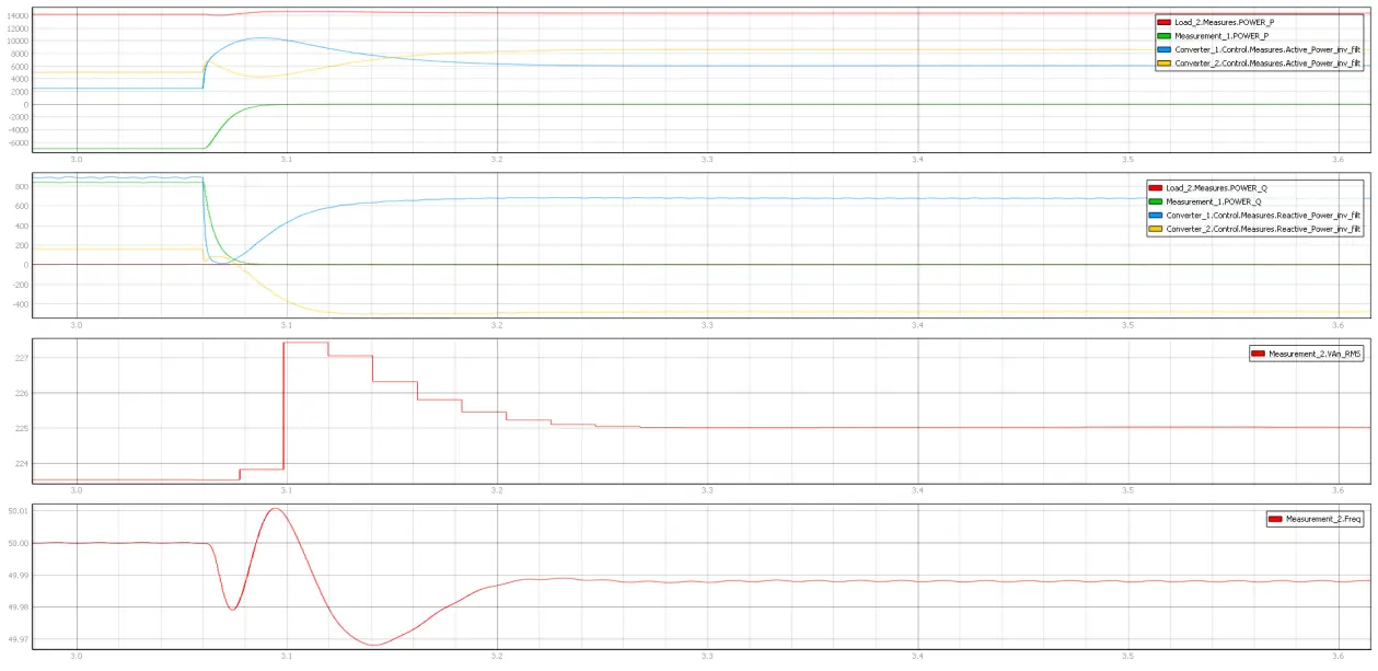 Figure 24: Active and reactive power while the grid is being disconnected.
In an isolated microgrid the power is split between the two converters and the original setpoint ratio is no longer respected — the line parameters between the inverters influence the power distribution. The converters exchange reactive power because the droop algorithm tries to maintain the reference voltage at their outputs, which is impossible due to the voltage drop on the line. Grid frequency drops slightly when connection to the main grid is lost, according to the droop coefficients.
5.5 Big load step with 2 GFM in islanded mode#
Both inverters are connected to the isolated microgrid with load 1 and setpoints 0 kW. A 15 kW load step is performed.
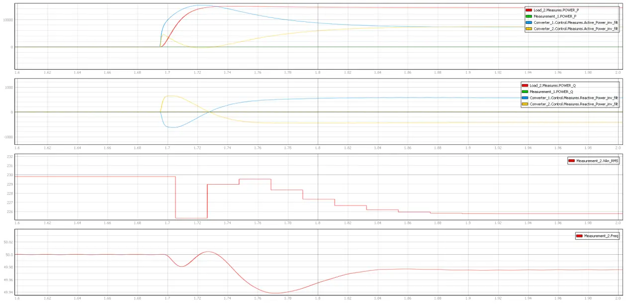 Figure 25: 15 kW load step in islanded operation, \(H_1 = H_2 = 0.001\).
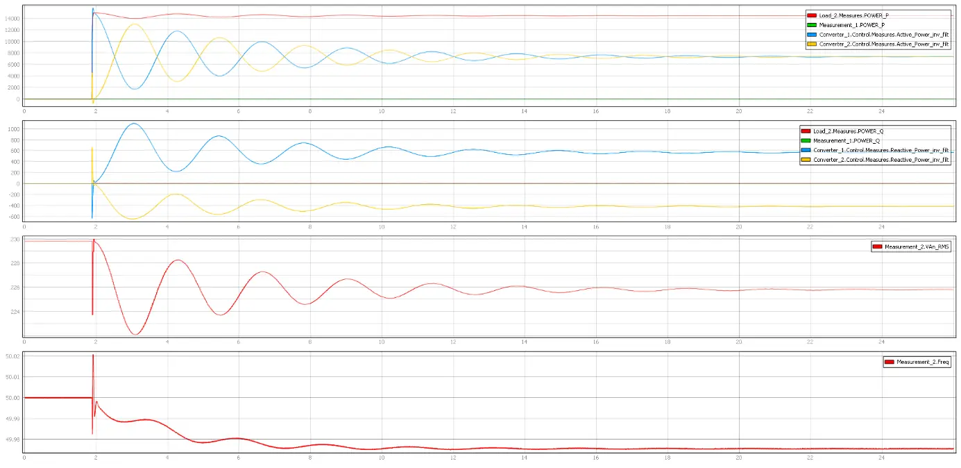 Figure 26: 15 kW load step in islanded operation, \(H_1 = H_2 = 1\).
After a transient in which the inverter directly connected to the load compensates most of the power, the active power balances on both inverters. Higher inertia increases system response time and causes oscillation. As the power consumed on the grid increases, the grid frequency decreases slightly, and the error in the frequency setpoint is converted into a voltage signal at the output of the inverter.
5.6 Two GFM in islanded mode: load sharing with different droop coefficients#
Both inverters are connected to the isolated microgrid with load 1 and setpoints of 0 kW, but with different frequency-droop coefficients. The microgrid operates islanded with the 15 kW load.
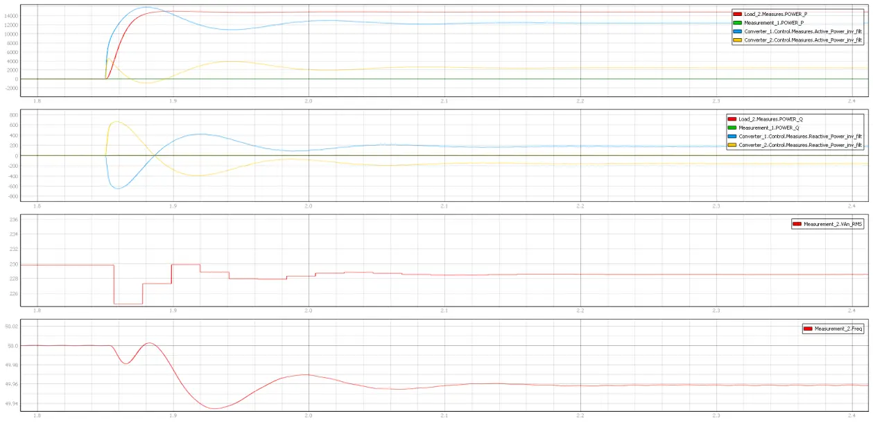 Figure 27: 15 kW load step with \(k_{f1}=0.001\) and \(k_{f2}=0.005\).
The droop coefficient for frequency control (\(k_f\)) is used to adjust the power distribution between the two inverters. With a 1:5 ratio between the two coefficients, the measured-power ratio is 5:1 — i.e. the active-power distribution is inversely proportional to the ratio of the droop coefficients of the two inverters.
6. Experimental results#
All experimental results obtained on the real infrastructure are documented in the WP5 report.