WP2 - Cybersecurity and risk assessment#
This work package addresses both cybersecurity and overall risks related to the Resinet project. That is, analyzing whether algorithms and systems are designed and deployed in a secure manner. In addition, risk analysis is to be applied to the overall architecture and fed to the DER algorithm to reduce risks in general.
WP2 — Final Report: Security and Risk Assessment#
Authors
Jan Huber, Luca Haab — December 19, 2025
1. Introduction#
1.1 Overall project#
The RESINET project aims to develop cyber-secure algorithms that enhance the resilience of distribution grids, enabling them to operate autonomously as “electrical islands” during emergencies and reconnect to the main grid under normal conditions, with seamless transitions between the two modes. It pursues three goals:
- Control & Scheduling — develop algorithms that synchronise and coordinate multiple distributed energy resources (DERs), optimising their operation in both grid-connected and islanded modes.
- Risk Analysis & Operational Practices — conduct a thorough risk assessment of microgrids and their components. Cybersecurity is a core consideration, shaping guidelines for safe deployment of grid-connected microgrids.
- Laboratory Validation — demonstrate the concepts on a lab-scale microgrid, proving the feasibility of the proposed methods.
Modern electrical grids operate through a combination of physical actions and economic optimizations to maximise efficiency while minimising disruptions. These functions may be initiated automatically, by operator dispatch, or through economic signals. Interoperability requirements for each operation vary based on temporal, spatial, and topological constraints. Utilities must adapt their architecture and operations to accommodate both new and legacy devices in a rapidly evolving environment influenced by policy and market decisions.
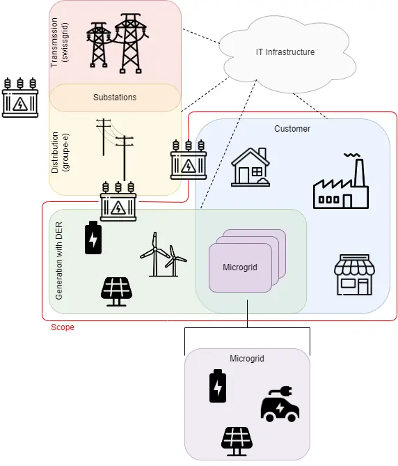 Figure 1: Microgrid and DER Scenario [NIST Smart Grid Interoperability Framework].
A summary of the challenges set forth in the NIST Smart Grid Interoperability Framework gives a useful contextual view of the project. On the demand side, interoperability is crucial to customer empowerment. Key challenges include:
- Information asymmetry — interoperability enhancements should reduce informational imperfections that traditionally favour producers over consumers, and better inform customers about their own electricity-use decisions and technological investments.
- Value stacking — customer assets that sit idle due to lack of outside options could be matched with new opportunities as interoperability increases and barriers to providing grid services fall.
- Customer choice — interoperability improvements can reduce barriers to entry and transaction costs paid by customers as they seek to integrate their equipment into the sector’s value network.
1.2 Power Grids#
The conceptual model from the main referenced document divides the grid into seven domains: Customer, Markets, Service Provider, Operations, Generation/DER, Transmission, and Distribution. Each domain represents a distinct role in producing, moving, managing, or consuming electricity.
Four scenarios are considered:
- Legacy — baseline reflecting traditional grid structures and current practice.
- High-DER — future-leaning view where DERs provide substantial power, requiring better coordination across both distribution and transmission levels.
- Hybrid — high-DER environment combining centralised, distributed, and edge control, using both private and public communication networks.
- Microgrids — examples of customer-managed and utility-managed microgrids, with varied ownership models and interface points with the larger grid.
These scenarios illustrate how communication routes, responsibilities, and interoperability evolve, and emphasize the growing role of distributed resources. As the grid incorporates new technologies and a broader range of participants, its attack surface expands, increasing the importance of cybersecurity.
A detailed summary of the NIST Smart Grid Interoperability Framework can be found on the project homepage and on the dedicated GitLab repository.
2. Cybersecurity & Risk Assessment#
The literature surveyed represents the current state-of-the-art in microgrid cybersecurity, spanning architectural reviews, communication-layer analysis, resilience research, standards documents, and early-stage threat-modelling approaches.
2.1 Standards & guidelines for protecting a microgrid infrastructure#
Many standards and guidelines apply to microgrids; those that aim at supporting cyber-secure operation are of primary interest. The IEC/ISA 62443 standard is an encompassing framework that covers the full spectrum of activities: from development of products and services to the operation of solutions.
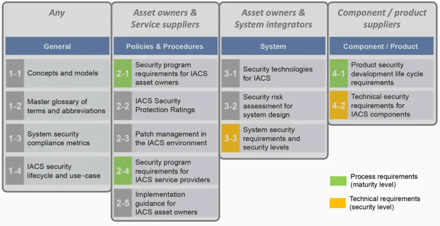 Figure 2: IEC/ISA 62443 Stakeholders.
Following such standards positions an entity to comply with directives such as
EU 2022/2555 (NIS2) and similar. Critical infrastructure is highly
policy-driven, with different countries defining their own requirements.
However, a solid foundation based on an overarching standard facilitates
compliance with country-specific obligations. The main challenge is the
standard’s size and complexity, which highlights the need for guidelines that
simplify implementation by distilling its essential elements.
Figure 2: IEC/ISA 62443 Stakeholders.
Following such standards positions an entity to comply with directives such as
EU 2022/2555 (NIS2) and similar. Critical infrastructure is highly
policy-driven, with different countries defining their own requirements.
However, a solid foundation based on an overarching standard facilitates
compliance with country-specific obligations. The main challenge is the
standard’s size and complexity, which highlights the need for guidelines that
simplify implementation by distilling its essential elements.
For assessing an organization’s cybersecurity posture, both lightweight approaches — such as the Swiss NCSC Recommendations ICT minimum standard and its Excel-based tool — and more comprehensive frameworks, such as the ENISA CSIRT maturity framework, attracted attention and have been integrated into the project toolsets. Notably, the Swiss NCSC Recommendation became mandatory during the development of the present project as part of the “Bundesgesetz über die Informationssicherheit”.
2.1.1 IEC/ISA 62443 Example#
While the project does not aim to incorporate all IEC 62443 documents into an Excel tool, its objective is to map selected requirements into dedicated sections of a supporting tool. As a practical validation, one component of the standard was selected and a separate tab was created for each practice. The example below shows the mapping of IEC 62443-4-1, Practice 8 (“Security Guidelines”).
This approach provides a valuable tool for both assessing the current state and supporting implementation, enabling tracking of requirement status while consolidating each requirement and its supporting guidance in a single, accessible location.
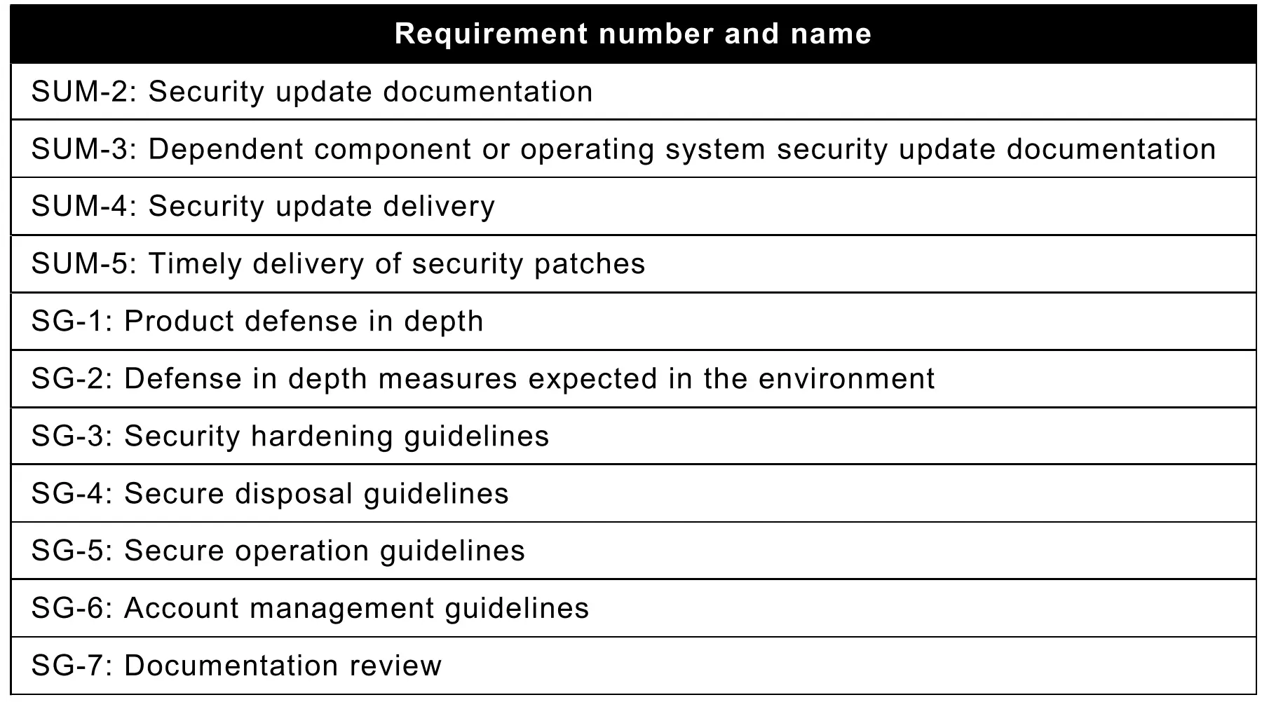 Figure 3: IEC/ISA 62443-4-1 requirements to Excel mapping.
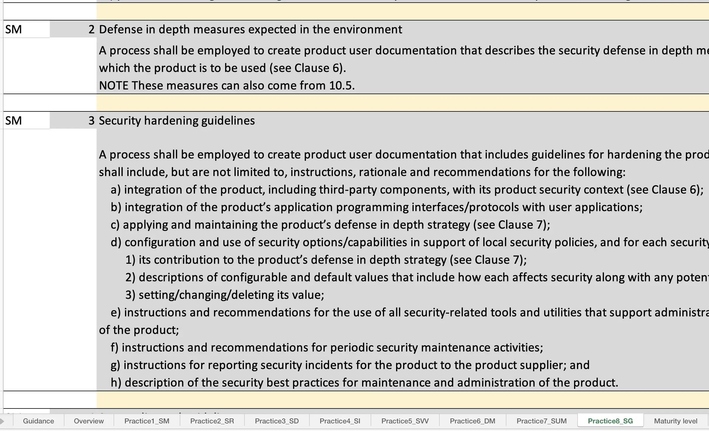 Figure 4: Assessment of IEC 62443-4-1, Practice 8 “Security Guidelines” Maturity.
This work is available for IEC 62443-4-1 but can be readily extended to
the other parts of IEC 62443. The rationale for selecting this part as an
example is that the project aims to develop algorithms intended for integration
into products: IEC 62443-4-1 “Secure product development lifecycle
requirements” is a prerequisite for IEC 62443-4-2 “Technical security
requirements for IACS components”, making it the logical starting point.
Figure 4: Assessment of IEC 62443-4-1, Practice 8 “Security Guidelines” Maturity.
This work is available for IEC 62443-4-1 but can be readily extended to
the other parts of IEC 62443. The rationale for selecting this part as an
example is that the project aims to develop algorithms intended for integration
into products: IEC 62443-4-1 “Secure product development lifecycle
requirements” is a prerequisite for IEC 62443-4-2 “Technical security
requirements for IACS components”, making it the logical starting point.
2.2 Network Design#
The tension between strong security and ease of use is not unique to this project. Zero Trust Architecture was initially considered; however, its limited maturity for OT applications, together with the associated costs (OPEX and CAPEX), led to the selection of the Purdue Model instead. This approach is also compatible with IEC 62443. The overarching objective is to specify a solution that is both simple and cost-effective — further motivated by the fact that many power grid devices lack the computational and architectural capabilities required to support modern security paradigms such as Zero Trust Architecture.
2.2.1 General model#
Following the principles defined in IEC 62443 standards — where the infrastructure is divided into zones (logical or physical groupings of assets sharing common security requirements) and conduits (logical groupings of communication channels connecting two or more zones) — different dimensions are considered:
- Identification and Authentication Control (IAC)
- Use Control (UC)
- System Integrity (SI)
- Data Confidentiality (DC)
- Restricted Data Flow (RDF)
- Timely Response to Events (TRE)
- Resource Availability (RA)
In the present project, we focus primarily on SI, IAC, and RDF, with a limited focus on RA. By implementing robust network segmentation, defence-in-depth strategies, access control mechanisms, and secure communication protocols, we address a significant portion of the security requirements envisaged by IEC 62443.
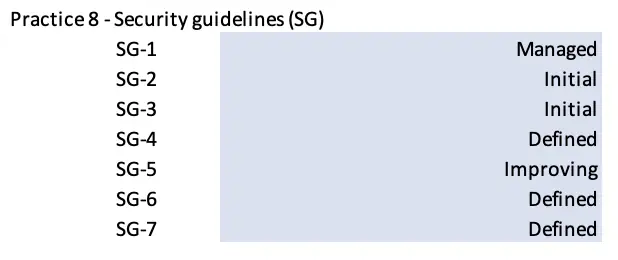 Figure 5: Network Reference Model (PERA).
2.2.2 GridLab implementation#
The GridLab infrastructure emulates a multi-level power system comprising high-voltage (HV), medium-voltage (MV), and low-voltage (LV) domains, electrically scaled to a nominal 400 V level to enable practical laboratory testing, uniform instrumentation, and safe operation.
2.2.3 Services#
A network presents many services. The following covers those relevant to the functioning of the infrastructure.
Domain Name System (DNS)
DNS maps human-readable names (like server.example.com) to IP addresses.
Typically, these records are static; however, dynamic DNS allows automatic
updates. When a device’s IP address changes — common when using DHCP — it
sends an update to the DNS provider, which ensures that the hostname always
points to the current IP.
The DNS protocol offers limited protection against malicious or forged responses. DNS Security Extensions (DNSSec) addresses this by adding digital signatures into DNS data so that each DNS response can be verified for integrity and authenticity.
Naturally, this requires that the validating resolver itself is not spoofed or compromised. Alternatively, a client with DNSSec support can verify the signature chain directly from the root zone down to the domain, avoiding reliance on any potentially untrusted intermediary.
Dynamic Host Configuration Protocol (DHCP)
DHCP automates network configuration. When a device joins a network, it broadcasts a request. The DHCP server replies with a lease that includes an IP address from the configured pool, the subnet mask, default gateway, and DNS servers. The lease includes a timer that the client must renew before expiry, centralizing control of IP addressing and preventing conflicts, while still allowing static reservations.
MODBUS
MODBUS is a widely adopted standard for connecting sensors, actuators, and controllers in industries such as manufacturing, energy, and transportation. Its architecture is a simple client-server protocol designed for limited computing resources. Communication occurs through structured messages containing a slave address, a function code (read/write), and data, typically transmitted over serial or Ethernet. Slaves cannot initiate communication and only respond when queried by the master.
However, MODBUS does not natively support encryption, authentication, or integrity protection. The Modbus Security Protocol specification provides encryption, integrity, and mutual authentication, but it requires a PKI and TLS (≥1.2) support on each end-device — conditions that cannot be guaranteed in every embedded deployment.
Modbus Security — deferred in this project
In the GridLab environment, Modbus Security Protocol was not implemented because not all devices support TLS or have sufficient compute resources. Combined with concerns about Energy Management System latency, this was deferred. Future implementations should address the following:
- Device resources — sufficient headroom for TLS with no impact on determinism, availability, or safety.
- Certificate lifecycle management — devices deployed for 10–25 years must have certificates renewed every 1–3 years; failing to handle this correctly risks serious service disruptions (cf. Ericsson 4G outage, 2018).
- Device secrets protection — devices may lack a TPM, making private key storage vulnerable on physically accessible hardware.
- Time and clock issues — TLS and PKI require correct time for X.509 certificates and revocation mechanisms (CRL, OCSP) to function.
- Interoperability and legacy devices — old devices with no upgrade path may need to retain insecure protocols but be placed in segments under stricter scrutiny.
Other services
Many other protocols could have been assessed given the large number used in the field. The aspects considered here are common and can be generalized: operational constraints must be carefully examined when evaluating a secure variant of any service, as a secure implementation may function smoothly on one device but fail on another due to resource limitations or absent features.
2.2.4 Defenses#
Network Switching#
Switch hardening aims to protect a network switch from misuse, attacks, and unauthorized access by enforcing strict control over traffic behaviour and device identification. Relevant techniques include:
- Port Security — prevents MAC address table exhaustion by limiting the number of addresses a port may learn, blocking untrusted devices and MAC-flooding attacks.
- Port isolation — restricts which ports are allowed to communicate with each other, reducing lateral movement and minimising the attack surface within the broadcast domain.
- Access Control Lists (ACLs) — enforce traffic filtering at the switch. MAC ACLs filter at Layer 2 (MAC address, VLAN, EtherType); Standard IP ACLs operate at Layer 3 (IP addresses) to restrict which hosts or networks may communicate.
- IP-MAC Binding — ties together the IP address, MAC address, VLAN ID, and switch port for a device. Only devices matching their registered binding entries are allowed network access.
- ARP Inspection — validates ARP traffic against the IP-MAC binding table to stop forged ARP information from poisoning ARP caches. Prevents attacks such as: gateway impersonation, Man-in-the-Middle injection, and ARP flooding.
- ARP Defend — when ARP traffic becomes excessive, temporarily suspends ARP acceptance on a port to prevent flooding from overwhelming the switch.
Network Routing#
Routing hardening focuses on protecting a network router from misuse, primarily targeting Layer 3 and above by controlling packet forwarding, securing routing information, and enforcing security policies between network segments. Pertinent elements include:
- Routing Control and Routing Protocol — ensures only legitimate routing information is accepted and propagated.
- Access Control Lists and Packet Filtering — IP ACLs filter traffic based on source/destination IP, protocol, and port; Anti-Spoofing ACLs drop packets with invalid internal source addresses arriving from external interfaces; Traffic Rate Limiting prevents bandwidth exhaustion from floods.
- Stateful Firewall Inspection — tracks active connections and only allows traffic belonging to valid sessions. Enables connection tracking, application- aware filtering, and zone-based firewalling. Can also be used for NAT to obfuscate internal IP addresses and control exposed services.
- Intrusion Detection and Prevention (IDS/IPS) — monitors traffic and alerts (IDS) or actively drops malicious packets (IPS). In our context, IDS is often preferable as it does not interrupt critical traffic that may have been misclassified.
2.3 Threat modeling and code analysis#
Securing an infrastructure and its associated devices is a complex task that quickly becomes apparent upon examination.
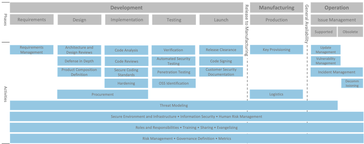 Figure 9: R&D activities.
To address the various aspects of security, the IEC/ISA 62443 standard covers
the full spectrum of challenges. In our case, the main objectives are: ensuring
sound threat models so that correct countermeasures can be realized, and
providing code-analysis support as new converter models are developed. These
correspond to the System and Product parts of IEC/ISA 62443 (3-3 and 4-1
respectively). Should the work be extended, following the guidelines in those
standards would be highly beneficial.
Figure 9: R&D activities.
To address the various aspects of security, the IEC/ISA 62443 standard covers
the full spectrum of challenges. In our case, the main objectives are: ensuring
sound threat models so that correct countermeasures can be realized, and
providing code-analysis support as new converter models are developed. These
correspond to the System and Product parts of IEC/ISA 62443 (3-3 and 4-1
respectively). Should the work be extended, following the guidelines in those
standards would be highly beneficial.
2.3.1 Threat model#
Regulations#
Two key regulations provide cybersecurity guidance for DER environments:
IEEE 1547.3-2023 — Guide for Cybersecurity of Distributed Energy Resources Provides recommendations and best practices for securing communications, control, and data exchange between DERs and the grid, covering threat considerations, protections such as authentication and encryption, and cybersecurity-related aspects of DER integration. Intended for utilities, DER owners/operators, system integrators, and equipment manufacturers.
IEEE 2030.5-2018 — Standard for Smart Energy Profile Application Protocol Defines a communication protocol (application layer profile) for interoperable, secure data exchange between the smart grid and its users, covering demand response, load control, price communication, distributed generation, energy storage, and electric vehicle integration. Built on TCP/IP and common internet protocols using RESTful architecture.
Existing approaches#
Several reports focus primarily on planning, engineering, and best-practice guidance for microgrid cybersecurity. While these documents provide valuable design practices, they rarely offer structured methods for threat modelling. Technical reviews such as those by Aghmadi et al. (2023), Canaan et al. (2020), and Jamil et al. (2021) provide broad summaries of adversary techniques, attack surfaces, and defensive approaches across DERs and grid-connected microgrids, but typically only outline the problems without offering structured threat-modelling frameworks.
The NIST TIR 7628 series brings a more formal approach to smart grid risk assessment and requirements engineering, but its scope is intentionally high-level and does not provide concrete guidance tailored to the operational dynamics of modern microgrids.
Other works examine cyber-attack impacts on microgrid control, stability, and resilience at the control and power-system levels, but they do not provide a systematic method for identifying or categorizing threats across the entire cyber-physical system.
For this reason, the paper “Threat Modelling of Cyber-Physical Systems — A Case Study of a Microgrid System” (Khalil et al., 2023) was chosen as the foundation. This paper directly illustrates how threats map into system behaviour and applies a formal threat-modelling method to an actual microgrid architecture, providing the most complete and directly applicable methodological basis.
Creating a tailored approach#
Due to the lack of a dedicated state-of-the-art methodology for cybersecurity in microgrids as cyber-physical systems, a tailored threat-modelling approach was developed. The method — implemented first in Excel and later in a web application — is inspired by Khalil et al. (2023) and designed to capture threats, vulnerabilities, and mitigations across cyber and physical layers in a structured, traceable way.
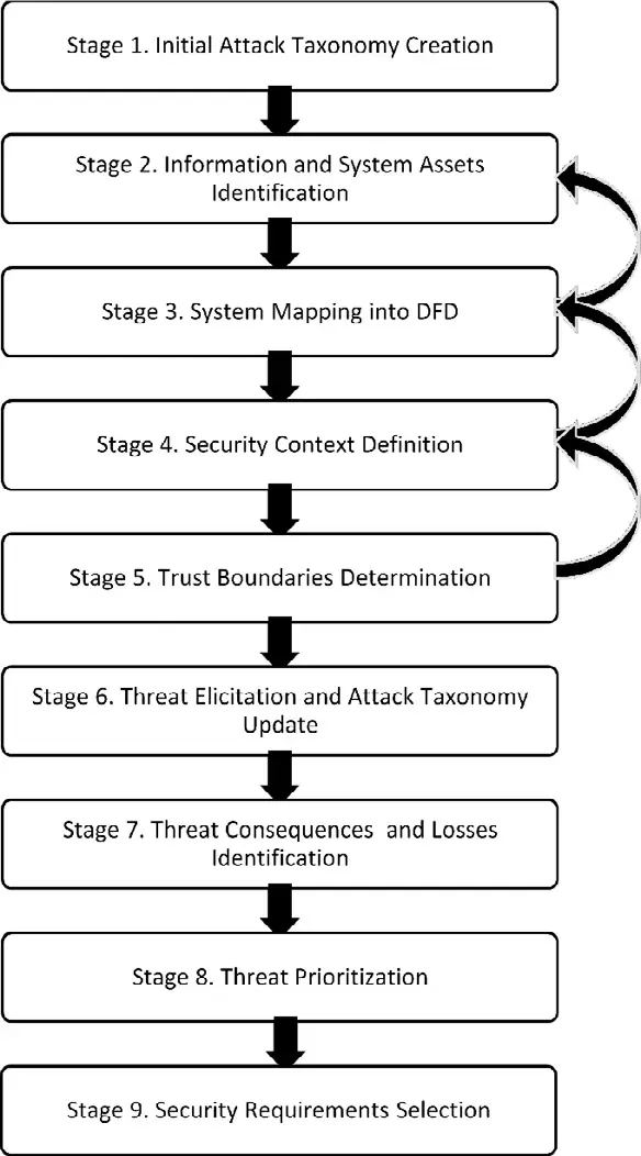 Figure 10: Methodology.
Stage 2 can be supported with the creation of a simple Block Diagram, which
can then serve as the basis for the Data Flow Diagram (DFD). Stage 6 is the
actual Threat Elicitation step:
Figure 10: Methodology.
Stage 2 can be supported with the creation of a simple Block Diagram, which
can then serve as the basis for the Data Flow Diagram (DFD). Stage 6 is the
actual Threat Elicitation step:
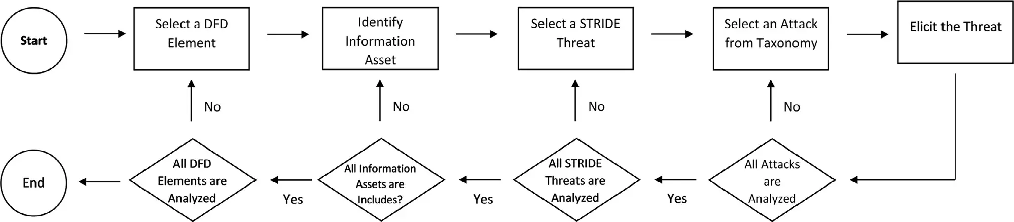 Figure 11: Threat Elicitation.
The implementation proceeds through eight steps:
Figure 11: Threat Elicitation.
The implementation proceeds through eight steps:
Step 1 — Attack Taxonomy. The original methodology uses a tree-like diagram, but we prefer a simple table with four columns: Precondition, Vector, Impact, and Mitigation.
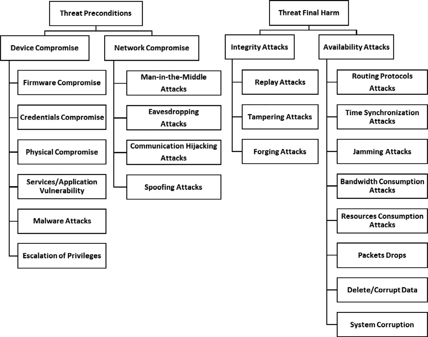 Figure 12: Attack taxonomy.
Step 2 — Asset identification in conjunction with the creation of a
Block Diagram.
Figure 12: Attack taxonomy.
Step 2 — Asset identification in conjunction with the creation of a
Block Diagram.
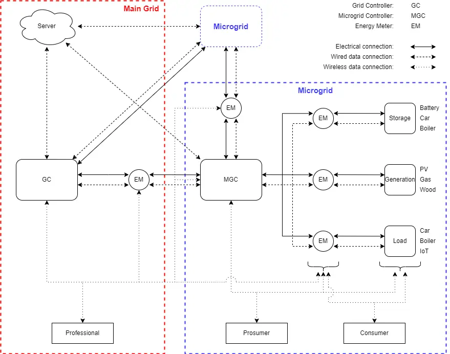 Figure 13: Asset identification.
Assets are broken down into system assets and information assets, both
listed in tables:
Figure 13: Asset identification.
Assets are broken down into system assets and information assets, both
listed in tables:
| Type | ID | Name |
|---|---|---|
| Software Related Process | SP-1 | Server |
| Software Related Process | SP-2 | Grid Controller |
| … | … | … |
Table 1: System assets table.
| Category | Sub-Category | ID | Description |
|---|---|---|---|
| Operational Data | Measurement Data | OD-1 | Data collected from Multimeters |
| Operational Data | Alarm Data | OD-2 | Data representing alarm states and status codes |
| … | … | … | … |
Table 2: Information assets table.
Step 3 — Textually define the security context.
Step 4 — Create the DFD and add trust boundaries.
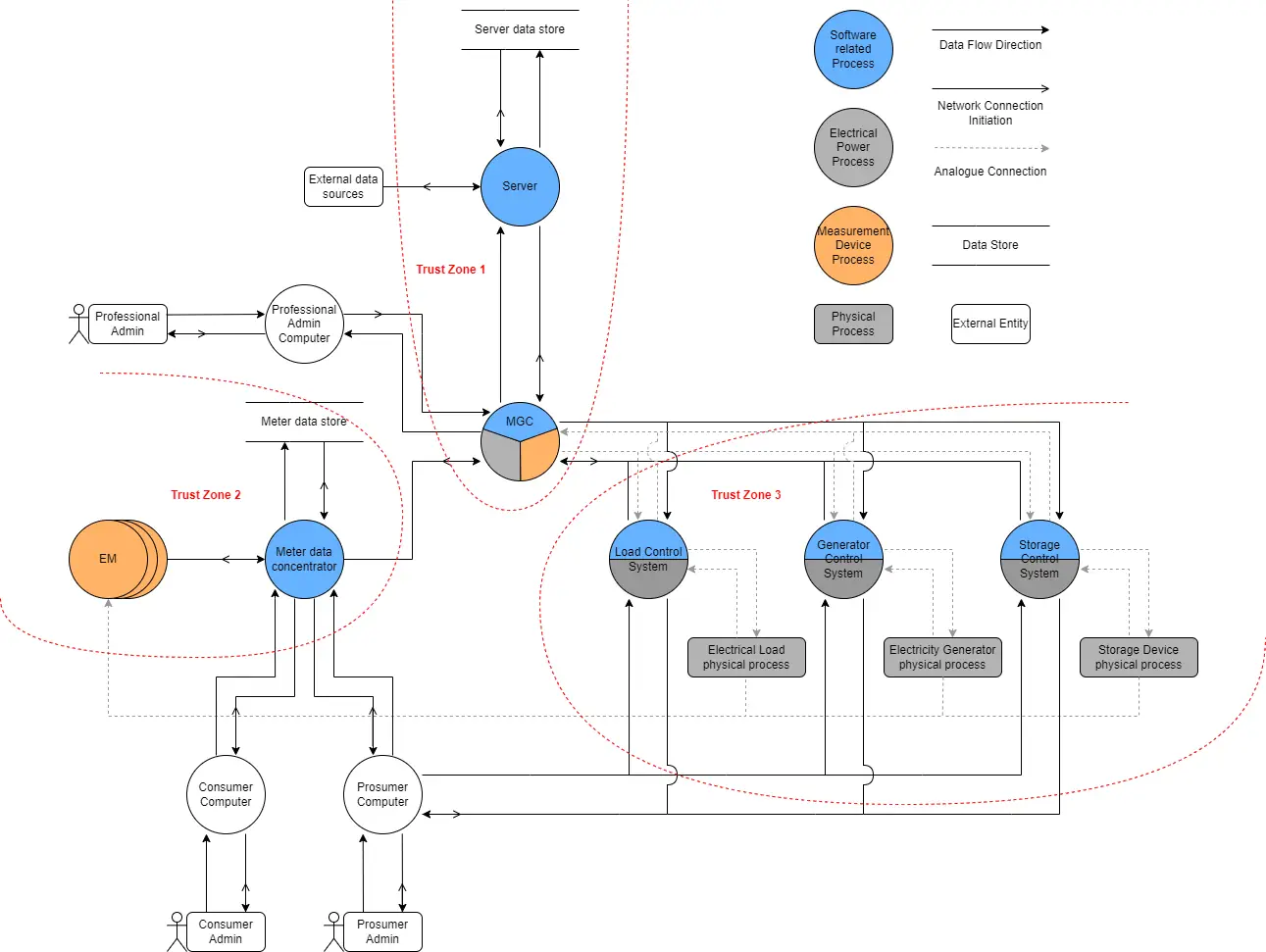 Figure 14: Trust boundaries.
Step 5 — Threat Elicitation following the original flow chart, producing
a table of all elicited threats:
Figure 14: Trust boundaries.
Step 5 — Threat Elicitation following the original flow chart, producing
a table of all elicited threats:
| DFD Element | Information Asset | STRIDE | Threat ID | Threat |
|---|---|---|---|---|
| Meter Data Concentrator | Operational Data, Metering Data, System Logs | S | T-MDC-S | A threat agent who compromises the network uses a spoofing attack to masquerade as the Meter Data Concentrator |
| … | … | … | … | … |
Table 3: Threat elicitation.
Step 6 — Enumerate potential Losses with priority levels (Critical / High / Medium / Low):
| Code | Loss Definition | Description | Priority |
|---|---|---|---|
| L-1 | Loss of life or injury to people | Cyberattacks on microgrids can lead to unsafe operating conditions | Critical |
| … | … | … | … |
Table 4: Potential losses.
Then list the potential consequences of the previously defined threats, and map losses to those consequences:
| Code | Threat Consequence | Description | Mapped Losses | C H M L |
|---|---|---|---|---|
| TC-2 | Disconnection from the microgrid | Cyberattacks can target breakers, protection relays, … | L-5, L-6, L-8, L-10 | 0 2 3 0 |
| … | … | … | … | … |
Table 5: Threat consequences.
Step 7 — Threat mapping: assign threat consequences to every threat, giving a criticality level to each one:
| Threat ID | Threat | Threat Consequence |
|---|---|---|
| T-EM-T | A threat agent who compromises the Energy meter manipulates/fakes metering data/system logs/configuration data. | TC-2 |
| … | … | … |
Table 6: Threat mapping.
Step 8 — Map threats to IEC 62443 Security Levels & Requirements. In this early stage this step was not developed and remains optional, but is important for future alignment with established standards.
Web-based Implementation of the Threat Modelling Approach#
While the initial threat-modelling framework was implemented in Excel, this format proved cumbersome for collaborative work, modularity, and repeated use. A prototype web-based application was developed, translating the Excel approach into a more flexible, interactive, and user-friendly platform.
The web app preserves the core methodology while providing several advantages:
- Collaboration — multiple users can contribute simultaneously, enabling a wider range of stakeholders (not only cybersecurity experts) to participate.
- Database integration — threats, assets, and mitigations are stored in a clean structured database, allowing easy querying, updating, and reporting.
- Reusability — core components, systems, and asset definitions can be reused across different microgrid models or projects, reducing setup time.
- User management — the platform supports configurable access levels for controlled collaboration and role-based participation.
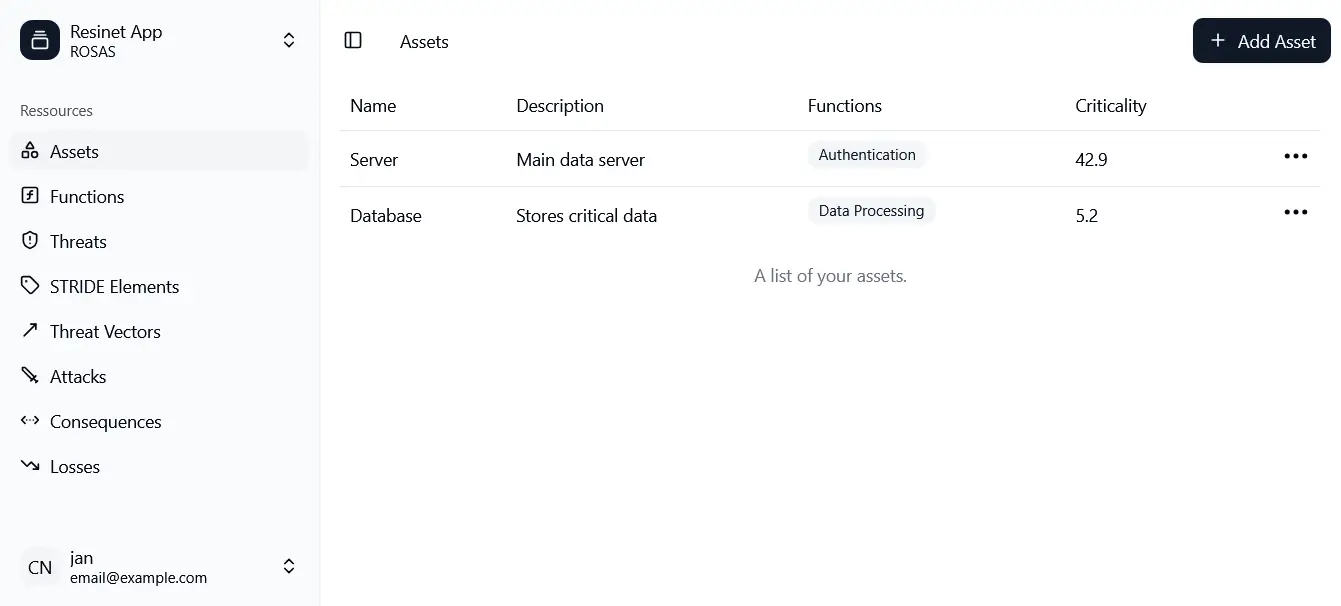 Figure 15: Web application — interface.
The element Functions was added in the web app as an abstraction of
physical assets within a microgrid, inheriting all threat consequences and
associated criticality levels. These functions can be attributed to real
assets by people who are not cybersecurity experts.
Figure 15: Web application — interface.
The element Functions was added in the web app as an abstraction of
physical assets within a microgrid, inheriting all threat consequences and
associated criticality levels. These functions can be attributed to real
assets by people who are not cybersecurity experts.
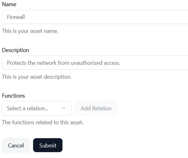 Figure 16: Web application — asset definition.
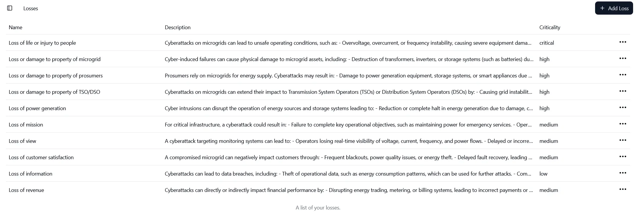 Figure 17: Web application — impact.
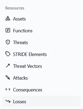 Figure 18: Web application — main resources.
At the end, all assets receive an automatically calculated criticality rating,
enabling identification of the most critical assets and prioritization of
mitigation work.
Figure 18: Web application — main resources.
At the end, all assets receive an automatically calculated criticality rating,
enabling identification of the most critical assets and prioritization of
mitigation work.
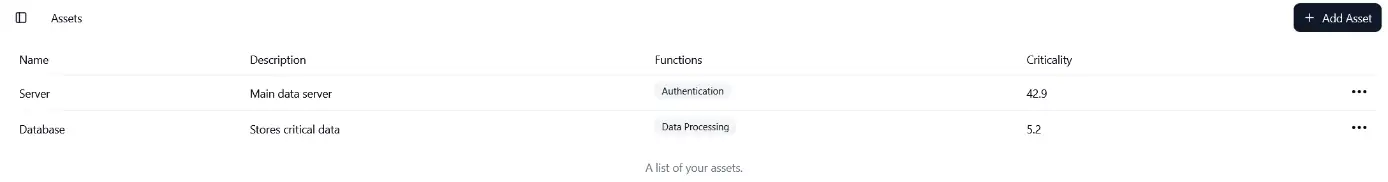 Figure 19: Web application — final assets page.
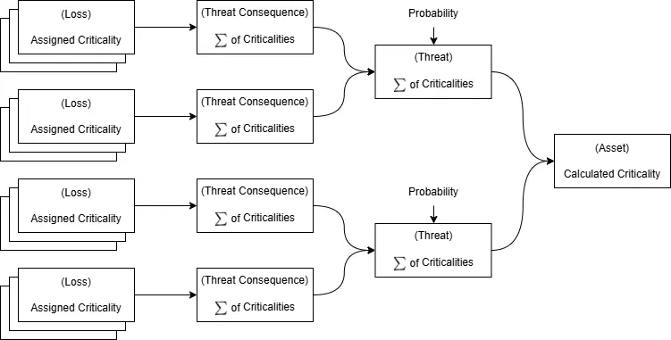 Figure 20: Web application — Criticality Calculation.
Criticality is calculated using the initial criticality assigned to the
relevant losses as well as the probability of each assigned threat. For the
time being, the resulting value should be interpreted as a rough indicator
rather than an absolute score.
Figure 20: Web application — Criticality Calculation.
Criticality is calculated using the initial criticality assigned to the
relevant losses as well as the probability of each assigned threat. For the
time being, the resulting value should be interpreted as a rough indicator
rather than an absolute score.
Access
The web app is accessible at http://resinet.isc.heia-fr.ch/ (from within HES-SO premises or via HES-SO VPN). The source code is on GitLab.
2.3.2 Code analysis#
Comparison of SAST tools#
A set of four static application security testing (SAST) tools was evaluated with a focus on C and C++ code analysis and their suitability for integration into Continuous Integration (CI) pipelines. The focus on C/C++ is motivated by the fact that most embedded devices are programmed in this language, either directly or through standards like IEC 61131-3, which ultimately generates C code during compilation.
Pipeline integration#
A concrete pipeline was implemented to check the code from WP4:
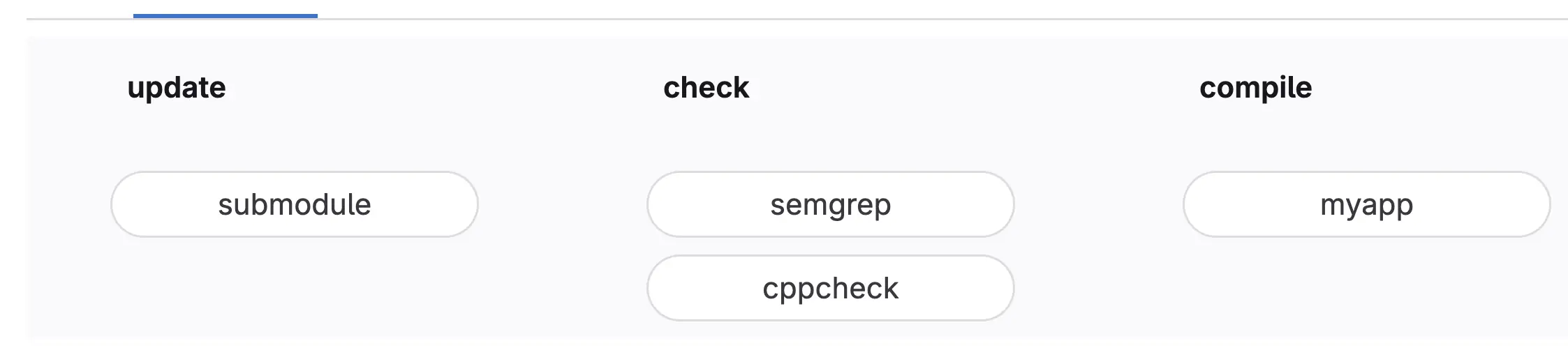 Figure 21a: CI SAST pipeline — stages: update → check → compile.
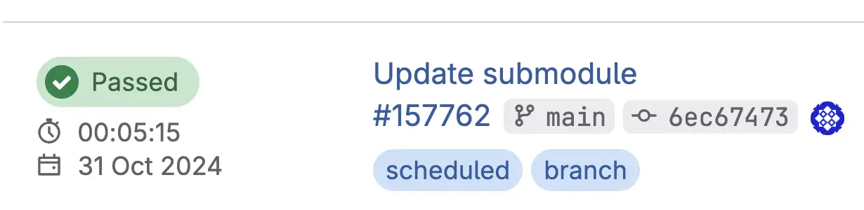 Figure 21b: CI pipeline — example of a passed run.
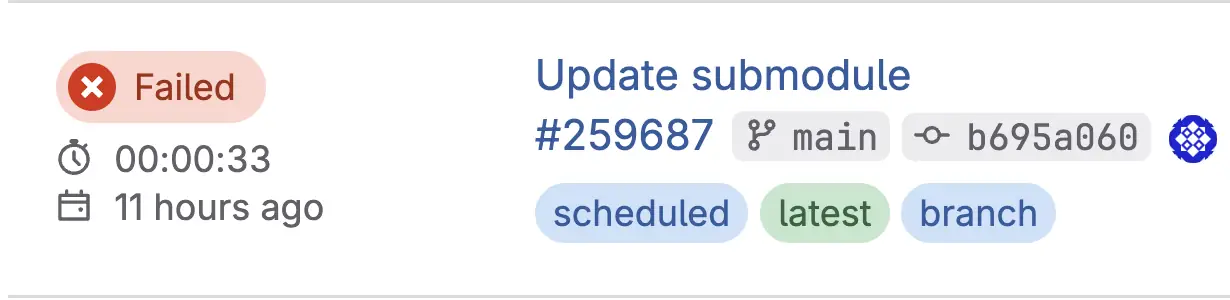 Figure 21c: CI pipeline — run detail.
One challenge encountered was that the team worked on the converter
application using the Typhoon HIL platform, while the CI pipeline analysed
the generated C code. Without direct access to the code generation platform,
this reflects a common industry challenge. Potential approaches include:
developing cooperation with supplier(s) to address identified issues; using
a standardized open platform; or patching generated code directly.
Figure 21c: CI pipeline — run detail.
One challenge encountered was that the team worked on the converter
application using the Typhoon HIL platform, while the CI pipeline analysed
the generated C code. Without direct access to the code generation platform,
this reflects a common industry challenge. Potential approaches include:
developing cooperation with supplier(s) to address identified issues; using
a standardized open platform; or patching generated code directly.
2.3.3 Starter Kit#
For ease of use, the project proposes a Starter Kit in the form of a web page that can be run locally on a PC, providing quick and easy access to the various resources developed in this WP.
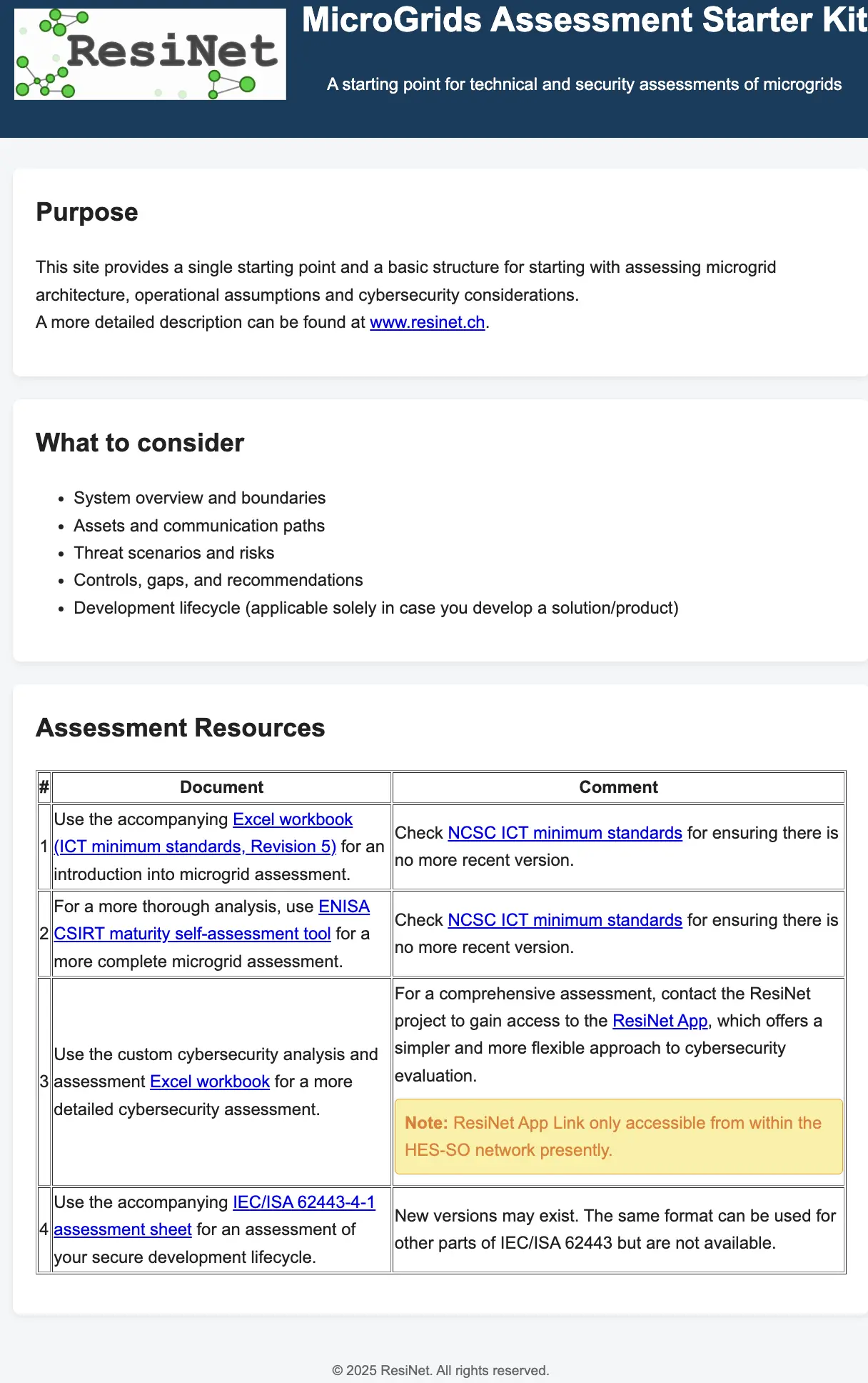 Figure 22: Starter Kit.
3. Setup & Testing#
During the tests, different options were employed, either in a replicated environment or in a real laboratory. For the real laboratory, the GridLab infrastructure presented in §2.2.2 was used. GridLab comprises multiple sections, but the project focused exclusively on the elements relevant to RESINET: batteries, the converter, and the energy management system.
Functional verification#
The services described in §3.2.1 were tested in the same way in the real lab. The network employs a mix of static IP addresses and dynamic leases — both functioned correctly and could access the Internet. As expected, machines within GridLab were not accessible from the HES-SO network (one of the objectives). Thanks to the segmentation implemented in this project, Layer 2 issues do not impact the HES-SO network, while Layer 3 issues can be contained via private IP addresses or quickly mitigated by adding dedicated firewall rules.
Attack identification#
The system is quite simple in its purest form: converter controllers, multiple inverters, battery controllers, and an Energy Management System communicating predominantly via MODBUS over Ethernet. Based on criticality, three main aspects were investigated:
- MODBUS — given its central importance in system functioning
- Name service — even if used mostly by the management system, incorrect data could significantly impact the optimization algorithm
- WAN services — ensuring attackers cannot penetrate the system remotely
DHCP attacks were not prioritized because the lab works mostly on statically allocated configurations. For a comprehensive reference, the MITRE ICS Attack Techniques list is an excellent resource.
Attack execution: process and cases#
Using freely available tools, the different phases of an attack were conducted: reconnaissance, intelligence analysis, and attack execution. The main cases addressed were:
- Forging of MODBUS packets (tampering) — correct packets from the network are sniffed and modified using scapy
- Replay of MODBUS packets — correct packets are sniffed and resent to the same recipient
- External access (WAN) — enumerate services and exploit potential weaknesses in used libraries or insecure protocols
- DNS substitution — substitute DNS with one under attacker control
The methodology applied: Pre-condition (running system with no interference) → Test (conduct attack, observe results vs. expected) → Post-condition (restore infrastructure to original state).
3.2.3 Hackathon: crowdsourcing attacks#
To validate the project’s outcomes, an event was organised where third-year Bachelor students of Computer Science at HEIA-FR, attending the course “Security of the infrastructures”, were asked to infiltrate the GridLab infrastructure. Students were given no information on the infrastructure or specific introductions to industrial protocols.
To ensure orderly microgrid operation during the attacks, a defined process was followed:
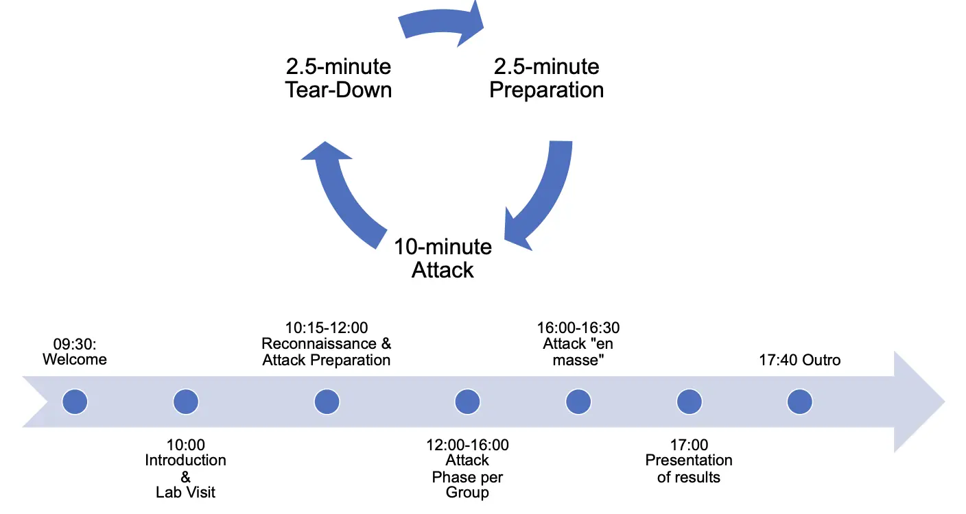 Figure 24: Hackathon process.
Figure 24
This figure uses the EMF vector format embedded in the source Word document,
which could not be auto-converted. Please extract it manually from the
source DOCX (20250821_WP2_report.docx) and save it as img/wp2_fig24_hackathon_process.png.
Certain machines were declared off-limits (e.g. the battery storage controller) due to their critical nature. The exercise was divided into two phases: attacks conducted from outside the GridLab and from within it, with the latter accounting for approximately 75% of the allocated time.
The results went beyond expectations. Students were capable of:
- Discovering all machines on the network
- Enumerating all exposed services
- Discovering services the lab owners were unaware of, and in some cases penetrating through them
- Leveraging the openness of MODBUS to forge packets and influence system behaviour
The main takeaways were:
- Asset inventory — the importance of maintaining an up-to-date inventory of physical and software assets and their configurations
- Access control — shared passwords bear significant consequences when compromised, especially if easily inferred
- Device resilience — some surprisingly recent devices could not withstand even simple attacks such as slow enumeration (one driver device rebooted when subjected to a slow scan)
- MODBUS — students with no prior knowledge of the protocol developed solutions capable of altering system behaviour within the 8-hour exercise. While repetition of control packets offered temporary protection, this would not have held up for long
The results, including descriptions of proceedings, tools, and scripts, are accessible on GitLab. Given the positive results, there is now a clear intention to repeat the exercise on a yearly basis.
4. Conclusion#
The project brings together control algorithms, cybersecurity risk assessment, and laboratory validation to strengthen the resilience of distribution grids. Within WP2, the work provides both a technical and security-focused foundation for microgrid deployment. By integrating international standards, building on cybersecurity-focused microgrid-specific literature, and validating solutions through a dedicated test bench, the work ensures that the proposed architecture is not only functional but also actually implementable.
The cybersecurity framework — developed first in Excel and later extended into a web-based application — demonstrates an interesting approach to usability and scalability. It bridges the gap between cybersecurity specialists, grid engineers, and grid technicians, enabling both expert-driven and operator-friendly assessments. This approach ensures that technical rigour is maintained while also making the framework practical for widespread adoption in the energy sector.
Ultimately, the work contributes to a systematic and replicable process for assessing and mitigating cybersecurity risks in interconnected microgrids. It lays the groundwork for deploying autonomous, cyber-resilient electrical islands that can maintain stability and reliability during both normal and emergency operating conditions.
4.1 Future Work#
Future work could focus on:
- Extending the cybersecurity framework web application prototype into a more robust and fully featured application with improved functionality and operational integration. The prototype has shown strong market interest from both field experts and IEC/ISA 62443 experts.
- Integrating fault tree analysis, given its relevance to availability within the cybersecurity framework.
- Continuing hardening of systems by providing a toolbox to automate security assessments and deepen cybersecurity posture.
- Implementing secure protocols in GridLab: MODBUS/TLS, DNSSEC, and more. The arrival of a new HIL platform should make adaptations easier.
- Making the hackathon a regular annual event for stress-testing the infrastructure under realistic attack scenarios.
- Addressing monitoring and alerting, critical components in such installations that deserve further attention.